Supercharge Your Innovation With Domain-Expert AI Agents!

Multi-stage flow control structure

A technology of flow control and concave structure, which is applied in the direction of capping with auxiliary devices, packaging, sealing parts with unloading devices, etc., which can solve the problems of waste of liquid materials, inconvenient use, and need for cleaning, etc.

Inactive Publication Date: 2017-05-24
GUANGDONG UNIV OF TECH
View PDF7 Cites 0 Cited by
  • Summary
  • Abstract
  • Description
  • Claims
  • Application Information

AI Technical Summary

Problems solved by technology

However, this method has an additional operation procedure, which requires cleaning after use, which not only brings inconvenience to use, but also causes waste of liquid materials

Method used


Image

  • Multi-stage flow control structure
  • Multi-stage flow control structure
  • Multi-stage flow control structure

Examples


Embodiment Construction

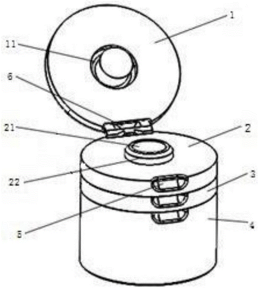
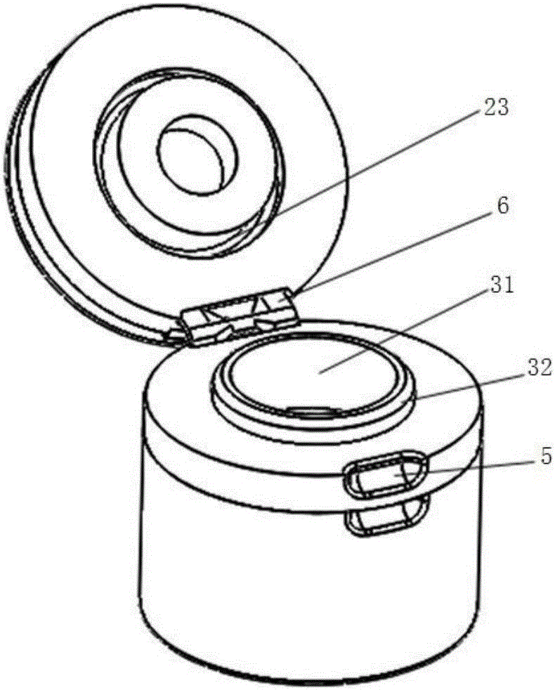
[0025] The invention provides a multi-stage flow control structure, and in particular relates to a container cover provided with multiple flow control layers, or a container including the container cover.

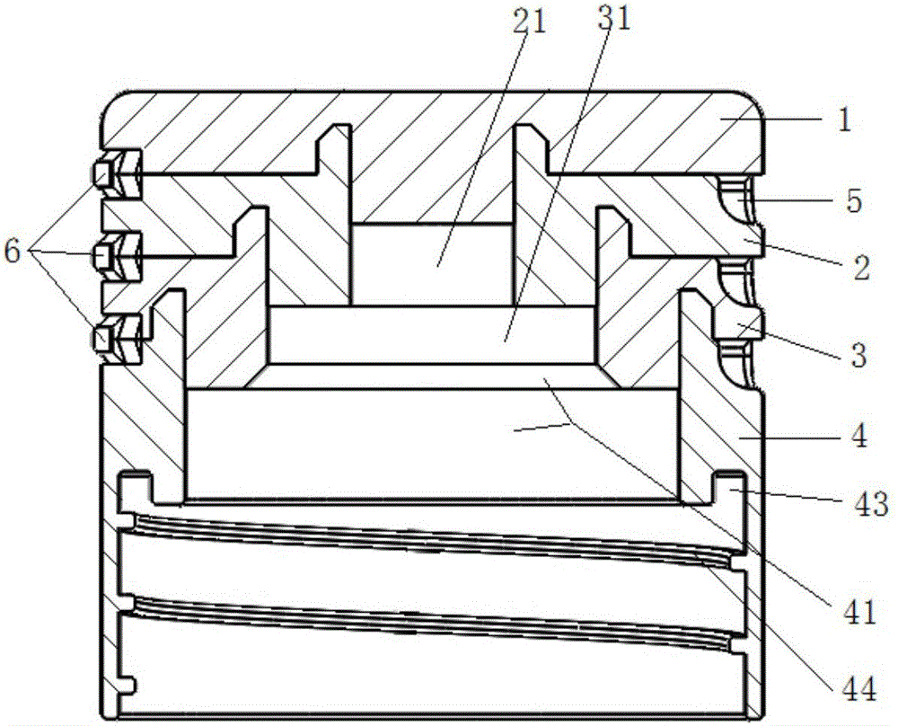
[0026] A multi-stage flow control structure provided by the present invention includes a cover plate and a multi-stage flow control layer;

[0027] The cover plate is socketed on the flow control layer;

[0028] The flow control layers at all levels of layer-by-layer sockets are equipped with limited flow ports;

[0029] The arrangement order of the calibers of the restrictors is as follows: they are arranged in order from small to large according to the direction in which the vertical distance between the flow control layer where they are located and the cover plate increases.

[0030] Further, the multi-stage flow control structure also includes: a connecting piece;

[0031] The connecting piece is arranged between the cover plate and the flow control layers of each lev...


PUM


Abstract

The application belongs to the technical field of flow control, and particularly relates to a multi-stage flow control structure. The multi-stage flow control structure disclosed by the invention comprises a cover plate and multistage flow control layers. The arranging sequence of flow limiting openings in the multistage flow control layers is as follows: the flow limiting openings are formed increasingly in apertures in a direction, the perpendicular distance with which is increased. By successively opening the cover plate and the flow control layers, the apertures of the flow limiting openings are successively switched increasingly to achieve a flow-limiting purpose. The structure can be used as a safe, sanitary, saving, practical and intelligent multistage flow control structure for a liquid material, and is quite humanized.

Description

technical field [0001] The invention belongs to the technical field of flow control, and in particular relates to a multi-stage flow control structure. Background technique [0002] Liquid material products on the market today, such as edible oil, laundry detergent, etc., are mostly packaged in simple plastic bags and cartons. The lid structure usually only serves as a seal, and cannot control the flow of liquid materials. Excessive outflow occurs. In view of this situation, one of the solutions is to set the lid of the packaging container as a cup-shaped lid for taking liquid materials. However, this method has an additional operation procedure, which requires cleaning after use, which not only brings inconvenience in use, but also causes waste of liquid materials. Contents of the invention [0003] In view of this, the object of the present invention is to provide a multi-stage flow control structure, which is used to prevent the liquid flow from being too large when t...

Claims


Application Information

Patent Timeline
IPC IPC(8): B65D47/08
CPCB65D47/08B65D2547/063
Inventor 余祖耀王梅曾路星郑淑英
Owner GUANGDONG UNIV OF TECH
Features
  • R&D
  • Intellectual Property
  • Life Sciences
  • Materials
  • Tech Scout
  • Unparalleled Data Quality
  • Higher Quality Content
  • 60% Fewer Hallucinations
Learn More