Novel excavator current-limiting control system

A current-limiting control, hydraulic excavator technology, applied in the direction of earth mover/shovel, construction, etc., can solve the problems of reducing engine utilization, unable to select hydraulic components, and restricting hydraulic parts selection, to increase flexibility performance, accurate current limiting control, and damage prevention

Active Publication Date: 2013-12-04
XCMG EXCAVATOR MACHINERY
View PDF5 Cites 0 Cited by
  • Summary
  • Abstract
  • Description
  • Claims
  • Application Information

AI Technical Summary

Problems solved by technology

[0002] At present, domestic excavator hydraulic components mainly rely on imports, and the selection of hydraulic components is greatly restricted. In order to meet the layout and performance requirements of the main engine, some main hydraulic components cannot be selected according to the desired specifications. type, it is difficult to achieve perfect matching of major components such as hydraulic pumps, valves, swing motors and travel motors
Especially in order to improve the working efficiency of the excavator, it is necessary to choose a pump with a large displacement to make full use of the power of the engine. At this time, the actuators such as the travel motor and the swing motor cannot choose a correspondingly large displacement due to space layout and other reasons. If Failure to limit current tends to reduce the service life of these actuators
Some host manufacturers choose to sacrifice the power utilization of the engine at this time to choose a pump with a smaller displacement, such as figure 1 As shown, at present, medium-sized excavators generally use series pumps, and the two pumps connected in series control different objects respectively. Usually, a single pump supplies oil for rotation, and two pumps supply oil separately for travel. flow, these actions must be identified and controlled in order to achieve the purpose of limiting the flow without reducing the utilization of the engine

Method used


Image

  • Novel excavator current-limiting control system
  • Novel excavator current-limiting control system

Examples


Embodiment Construction

[0013] The present invention will be further described below in conjunction with accompanying drawing.

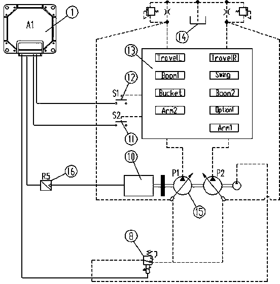
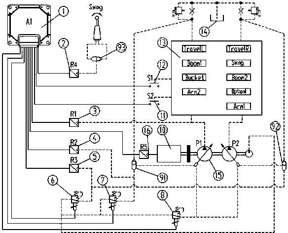
[0014] Such as figure 2 As shown, a new hydraulic excavator flow-limiting control system includes a main controller 1, a main pump proportional valve 8, an S2 getting off pressure switch 11, an S1 getting on a car pressure switch 12 and a speed sensor 16, and also includes a main controller and a main control valve respectively. Rotary pilot pressure sensor 2 electrically connected to device 1, P1 pump outlet pressure sensor 3, P1 pump flow limiting pressure sensor 4, P2 pump flow limiting pressure sensor 5, P2 pump maximum flow control proportional valve 6 and P1 pump maximum flow control proportional valve 7. The rotary pilot pressure sensor 2 is installed on the rotary pilot oil circuit where the shuttle valve III93 is located, and the rotary pilot pressure sensor 2 is a 50bar low pressure sensor. The maximum flow control proportional valve 6 of the P2 pump is connecte...


PUM


Abstract

The invention discloses a novel excavator current-limiting control system, belonging to the field of electrohydraulic control of hydraulic excavators. The novel excavator current-limiting control system comprises a master controller, a main pump proportional valve, a getting-down pressure switch S2, a getting-on pressure switch S1, and a rotation speed sensor and further comprises a revolution pilot pressure sensor, a P1-pump outlet pressure sensor, a P1-pump current-limiting pressure sensor, a P2-pump current-limiting pressure sensor, a P2-pump maximum-flow control proportional valve and a P1-pump maximum-flow control proportional valve, which are respectively and electrically connected with the master controller. The novel excavator current-limiting control system has the beneficial effects that: the flexibility in model selection of hydraulic elements can be enhanced, meanwhile, a rotary motor and a travelling motor can be prevented from being damaged by overlarge flow of a hydraulic system; in addition, the actions in need of current limitation can be judged through a detection device so as to prevent 'one size fits all' type current limitation, the pump displacement of two single pumps can be limited through controlling the current of the two current-limitation proportional valves, closed-loop control is adopted for a current control loop of the proportional valves, and thus the accurate current-lamination control is realized.

Description

technical field [0001] The invention relates to a novel excavator current limiting control system, which belongs to the field of electro-hydraulic control of hydraulic excavators. Background technique [0002] At present, domestic excavator hydraulic components mainly rely on imports, and the selection of hydraulic components is greatly restricted. In order to meet the layout and performance requirements of the main engine, some main hydraulic components cannot be selected according to the desired specifications. type, it is difficult to achieve a perfect match for major components such as hydraulic pumps, valves, swing motors, and travel motors. Especially in order to improve the working efficiency of the excavator, it is necessary to choose a pump with a large displacement to make full use of the power of the engine. At this time, the actuators such as the travel motor and the swing motor cannot choose a correspondingly large displacement due to space layout and other reas...

Claims


Application Information

Patent Timeline
Patent Type & Authority Patents(China)
IPC IPC(8): E02F9/22
Inventor 李亚东孟凡建刘立祥
Owner XCMG EXCAVATOR MACHINERY
Why Eureka
Try Eureka