Paper feeding device of die cutting machine

A technology of paper feeding device and die-cutting machine, which is applied in the directions of transportation and packaging, thin material handling, and separation of objects, etc., can solve the problems of being easily taken away by the paper-pushing claw, deviating from the cutting track of the die-cutting machine, and separating the cardboard, etc. The effect of saving resources, ensuring cutting quality and improving efficiency

Active Publication Date: 2017-05-24
重庆金凌印刷有限公司
View PDF8 Cites 4 Cited by
  • Summary
  • Abstract
  • Description
  • Claims
  • Application Information

AI Technical Summary

Problems solved by technology

But this device also has the following defects: the paper pushing claw is set in an L shape, and the paper pushing claw rotates along the chain. cutting machine cutting track

Method used


Image

  • Paper feeding device of die cutting machine
  • Paper feeding device of die cutting machine
  • Paper feeding device of die cutting machine

Examples


Embodiment Construction

[0019] The present invention will be described in further detail below by means of specific embodiments:

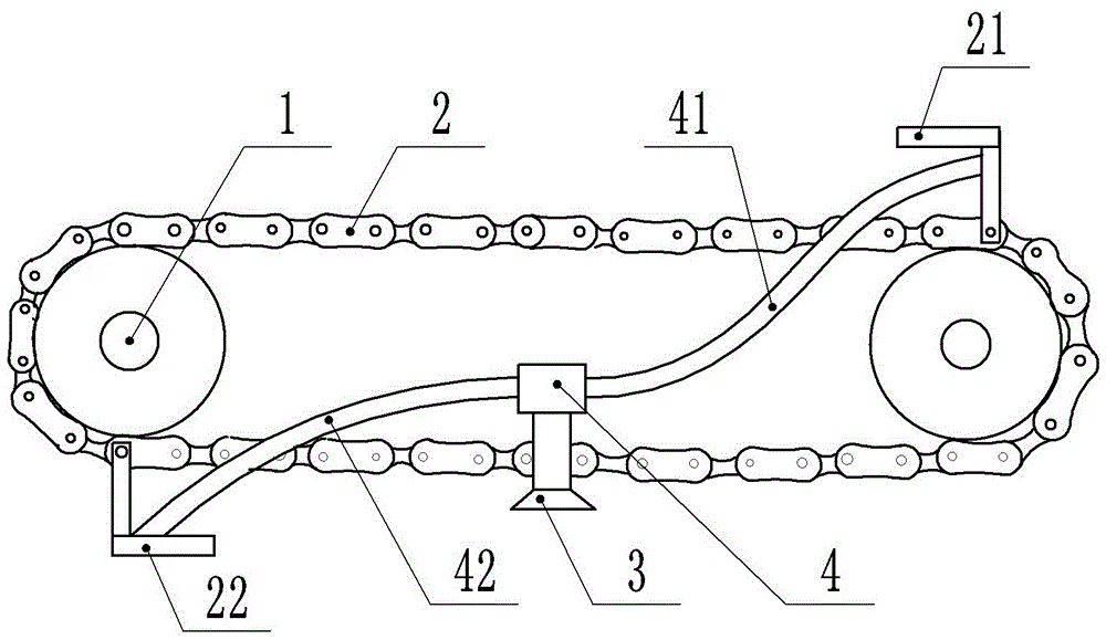
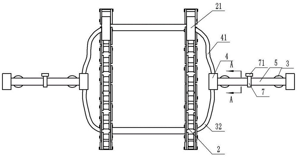
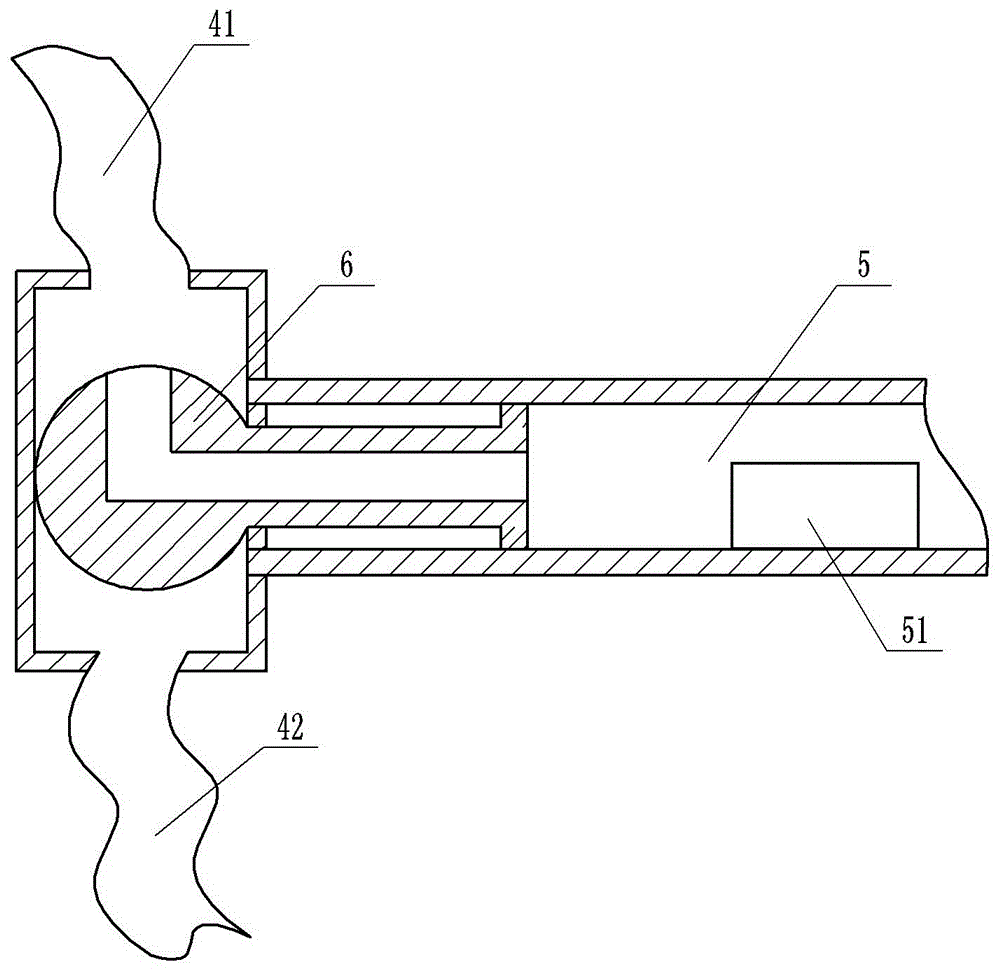
[0020] The reference numerals in the drawings of the specification include: sprocket 1, chain 2, first paper push claw 21, second paper push claw 22, first clamping plate 23, second clamping plate 24, groove 25, air bag 26. Spring 27, limit block 28, suction nozzle 3, rotating sleeve 4, first pipe 41, second pipe 42, rigid pipe 5, air extraction device 51, valve core 6, solenoid valve 7, solenoid valve controller 71 .

[0021] Such as figure 1 , figure 2 As shown, a paper feeding device of a die-cutting machine includes two symmetrically arranged paper feeding units, one paper feeding unit includes a rigid pipe 5, two suction nozzles 3, a first paper pushing claw 21, and a second paper pushing claw 22 , chain 2 and two sprockets 1, the chain 2 is set on the two sprockets 1 and meshed with the two sprockets 1; the first paper pushing claw 21 and the second paper pushin...


PUM


Abstract

The invention belongs to the technical field of feeding objects to machines and particularly discloses a paper feeding device of a die cutting machine. The paper feeding device of the die cutting machine comprises two paper feeding units. Each paper feeding unit comprises suction nozzles, a rigid pipeline, a first paper pushing claw, a second paper pushing claw, a chain and chain wheels. Each rigid pipeline is arranged on one side of the corresponding paper feeding unit. Each suction nozzle is downward and fixed to the corresponding rigid pipeline. An air exhaust device is arranged in each rigid pipeline. The two ends of each rigid pipeline are rotationally connected with rotating sleeves. A cavity communicating with the corresponding rigid pipeline is arranged in each rotating sleeve. A valve element is arranged in each rigid pipeline. One end of each valve element is fixed to one side of the corresponding rigid pipeline. The other end of each valve element is a ball matched with the corresponding rotating sleeve. Each ball is rotationally connected with the corresponding rotating sleeve. An L-shaped channel is formed in each valve element. Each rigid pipeline communicates with the corresponding rotating sleeve through the corresponding L-shaped channel. A first pipeline and a second pipeline are connected to the rotating sleeve. When the paper feeding device of the die cutting machine is adopted to feed paper, paperboards can be smoothly disengaged from the paper pushing claws, and the situation that the paper boards are taken away by the paper pushing claws and deviate from a cutting rail of the die cutting machine is avoided.

Description

technical field [0001] The invention belongs to the technical field of supplying objects to machines, in particular to a paper feeding device for a die-cutting machine. Background technique [0002] At present, the semi-automatic die-cutting machine used in the domestic market adopts the method of manual paper feeding when die-cutting cardboard, that is, the paper is fed through the rising of the rear paper pile, and then the paper that needs to be die-cut is fed one by one by manpower. into the die-cutting machine. This method of paper feeding requires direct human labor. When operating continuously, the operator is in a state of high concentration for a long time, the labor intensity is high, the operator is prone to fatigue, and has a high risk. Injury; At the same time, there are problems such as high die-cutting cost and low paper feeding efficiency. [0003] The Chinese invention patent with the publication number CN103771164A discloses a paper feeding device for a d...

Claims


Application Information

Patent Timeline
Patent Type & Authority Applications(China)
IPC IPC(8): B65H3/08B65H5/08
CPCB65H3/0816B65H3/0891B65H5/085B65H2406/36
Inventor 余喜玲
Owner 重庆金凌印刷有限公司
Why Eureka
Try Eureka