Check patentability & draft patents in minutes with Patsnap Eureka AI!

Buttonholing machine

A keyhole machine and machine body technology, applied in the field of sewing machines, can solve the problems of increased friction, transmission energy consumption, complex transmission structure, and increased production costs, and achieve the effects of reducing friction, solving complex structures, and convenient operation and use

Inactive Publication Date: 2017-05-24
贵州欣荣服饰有限公司
View PDF0 Cites 1 Cited by
  • Summary
  • Abstract
  • Description
  • Claims
  • Application Information

AI Technical Summary

Problems solved by technology

[0002] During the buttonhole process, the buttonhole machine drives the crank connecting rod, transmission shaft needle, crochet needle and feeding mechanism through the three-phase motor to sew and perform big eyes. After the sewing is completed, the thread is cut off. The existing buttonhole machine is driven by the transmission The connecting rod, the connecting rod drives the scissors on the upper surface of the keyhole sewing place to cut, because the long-term use of the transmission mechanism will cause wear or corrosion, and the friction force needs to be overcome when the double scissors cut, which greatly increases the friction force And the energy consumption of transmission, its transmission structure is also relatively complicated, maintenance is very inconvenient, maintenance cost is high, greatly increased production cost, and maintenance cycle is long, also affects production efficiency

Method used


Image

  • Buttonholing machine
  • Buttonholing machine
  • Buttonholing machine

Examples


Embodiment Construction

[0013] The invention will be further introduced below in conjunction with the accompanying drawings and specific embodiments.

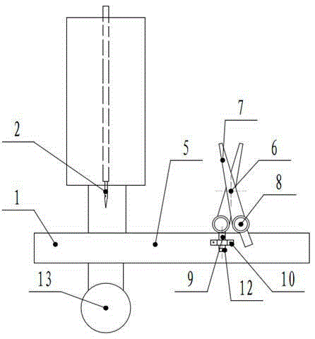
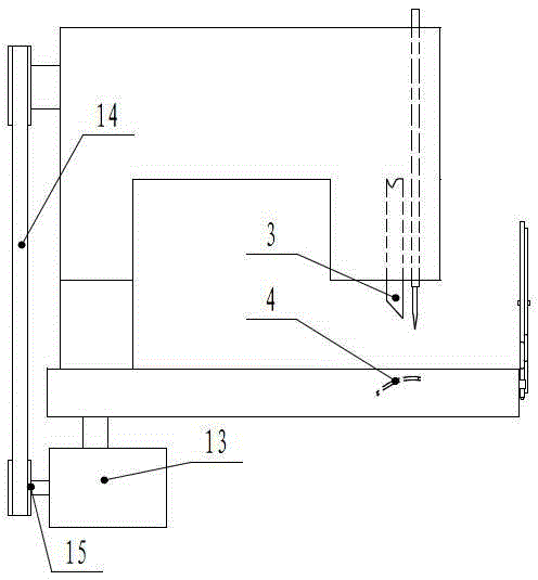
[0014] Such as Figure 1~3 As shown, a buttonhole machine includes a body 1, the body 1 has a machine needle 2 driven by a transmission mechanism driven by a two-phase motor 13, a hole knife 3 and a hook needle 4, and is fixedly installed on a machine platform 5, so that A detachable thread cutter 6 is placed on the front side of the machine table 5 .

[0015] Preferably, the above-mentioned thread cutter 6 includes mutually intersecting rotatable blades 7 and a ring handle 8, the ring handle 8 is provided with a pole 9, and the pole 9 faces the other side connected to the blade 7, and is connected with the The blade 7 remains on the same plane, and the middle finger or the ring finger are conveniently lapped on it when the thread is cut through the pole, which is labor-saving and easy to operate.

[0016] Preferably, the above-mentioned support rod...


PUM

PropertyMeasurementUnit
Lengthaaaaaaaaaa

Abstract

The invention discloses a buttonholing machine which comprises a machine body. The machine body is provided with a frame needle, a hole cutter and a thread hooking needle which are driven by a transmission mechanism driven by a two-phase motor, the machine body is fixedly installed on a machine platform, and a detachable thread trimmer is arranged on the front side of the machine platform. According to the buttonholing machine, the thread trimmer replaces an existing mechanical transmission up-down thread trimmer at a buttonhole, friction of mechanical transmission of existing equipment is greatly reduced, a three-phase motor is changed to be the two-phase motor which can also drive a sewing machine, the electric energy is greatly saved, the thread trimmer is detachably arranged on the front side of the machine platform, the thread trimmer can be picked and placed conveniently, the phenomena, caused by leaving the thread trimmer about, of losing and being difficult to find are avoided, the structure of the buttonholing machine is simplified, maintenance is more convenient, the maintenance cost is lower, the problems that in the prior art, due to the fact that he thread trimmer is installed, the structure is complex, the frictional force is large, much energy is consumed, maintenance is inconvenient, and the maintenance cost is high are effectively solved, and the buttonholing machine has the advantages of being simple in structure, convenient to operate, use, assemble and disassemble and low in price.

Description

technical field [0001] The invention belongs to the technical field of sewing machines, and relates to a buttonhole machine. Background technique [0002] During the buttonhole process, the buttonhole machine drives the crank connecting rod, transmission shaft needle, crochet needle and feeding mechanism through the three-phase motor to sew and perform big eyes. After the sewing is completed, the thread is cut off. The existing buttonhole machine is driven by the transmission The connecting rod, the connecting rod drives the scissors on the upper surface of the keyhole sewing place to cut, because the long-term use of the transmission mechanism will cause wear or corrosion, and the friction force needs to be overcome when the double scissors cut, which greatly increases the friction force And transmission energy consumption, its transmission structure is also relatively complex, maintenance is very inconvenient, maintenance costs are high, greatly increasing production costs...

Claims


Application Information

Patent Timeline
IPC IPC(8): D05B3/06
Inventor 周小军
Owner 贵州欣荣服饰有限公司
Features
  • R&D
  • Intellectual Property
  • Life Sciences
  • Materials
  • Tech Scout
  • Unparalleled Data Quality
  • Higher Quality Content
  • 60% Fewer Hallucinations
Learn More