Floor drain

A technology for floor drains and housings, applied in waterway systems, buildings, water supply devices, etc., can solve the problems of floor drains losing their seal and deodorization, and achieve the effect of preventing water return

Active Publication Date: 2017-05-24
新昌县佛虑机械配件厂
View PDF5 Cites 1 Cited by
  • Summary
  • Abstract
  • Description
  • Claims
  • Application Information

AI Technical Summary

Problems solved by technology

The water-sealed floor drain will lose the function of sealing and deodorizing due to the low water level or drying up after a period of time without water, and the floor drain will lose the function of sealing and deodorizing, thus requiring frequent replenishment of water and deodorizing, which will bring great inconvenience to users.

Method used


Image

  • Floor drain
  • Floor drain
  • Floor drain

Examples


Embodiment Construction

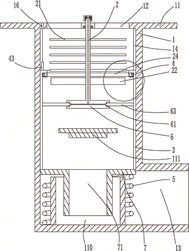
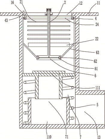
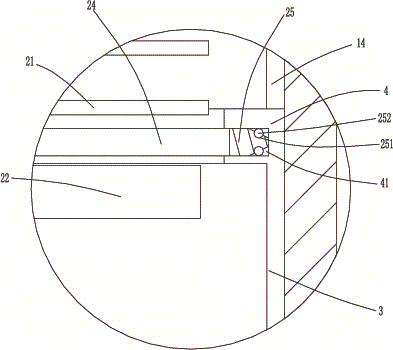
[0015] The present invention will be described in further detail below in conjunction with accompanying drawing and specific embodiment: see Figure 1 to Figure 7 , a floor drain, comprising a cylindrical housing 1, a flange 11 is provided on the top edge of the housing 1, a number of first through holes 12 are provided on the top of the housing 1, and a water outlet is provided on the side of the housing 1 13. The top of the housing 1 is rotated with a first rotating shaft 2, the first rotating shaft 2 is provided with an impeller 22, and the inner side of the housing 1 is vertically provided with several second chute 14, and several of the second A slide bar 3 is slidingly arranged in the chute 14, and a plurality of slide bars 3 upper ends are jointly connected with a slide ring 4, and the bottom of the first rotating shaft 2 is provided with a reel 6, and the reel 6 is provided with a ring The third chute 61, the third chute 61 is provided with a number of sliders 62, a nu...


PUM


Abstract

The invention discloses a floor drain. The floor drain comprises a cylindrical shell. A first through hole is formed in the top of the shell. A water discharge outlet is formed in the side face of the shell. A first rotating shaft is arranged at the top of the shell rotationally. An impeller is arranged on the first rotating shaft. Second sliding grooves are formed in the inner side of the shell. A sliding strip is arranged in each second sliding groove slidably. The upper ends of the sliding strips are connected to a sliding ring. A winding wheel is arranged on the first rotating shaft. An annular third sliding groove is formed in the winding wheel. Sliders are arranged on the third sliding groove, and are connected with the sliding strips through first pull ropes. Elastic bending pieces are arranged on the winding wheel. A push rod penetrates the first rotating shaft axially. The bending pieces are connected with the push rod through second pull ropes. The upper end of the push rod is elastically connected with the first rotating shaft through a second spring. A sliding plate is connected to the bottoms of the sliding strips. A water outlet pipeline is arranged on the sliding plate. A water accumulation groove is formed in the bottom of the shell. A first spring is arranged between the sliding plate and the shell. A sealing plug is arranged in the shell. By the floor drain, water backflow can be avoided effectively.

Description

technical field [0001] The invention belongs to the technical field of floor drains, in particular to a floor drain. Background technique [0002] The floor drain is a drainage device that connects the ground to the drainage pipeline system. It removes ground water, dust, fibrous matter, hair, and easy sediments. Most of the existing floor drains adopt the water-tight and odor-proof floor drains of the water return overflow structure. And the water-sealed floor drain will lose the function of sealing and deodorizing because the water level is too low or dries up after a period of time without water, and the floor drain will lose the function of sealing and deodorizing, thereby requiring frequent water replenishment and deodorizing, which brings great inconvenience to users. Contents of the invention [0003] The invention aims at the deficiencies of the prior art, and provides a floor drain, which can effectively prevent the floor drain from returning water, and prevent t...

Claims


Application Information

Patent Timeline
IPC IPC(8): E03F5/04
CPCE03F5/0407E03F2005/0416
Inventor 马建山
Owner 新昌县佛虑机械配件厂
Why Eureka
Try Eureka