Engine electric control oil supply device for model airplane and unmanned aerial vehicle

A fuel supply device and engine technology, applied in the direction of machines/engines, engine components, charging systems, etc., can solve the problem that the carburetor cannot absorb oil, reduce the endurance time, and cannot accurately control the fuel supply and fuel atomization Effect and other issues

Inactive Publication Date: 2017-05-24
石家庄益科创新科技有限公司
View PDF11 Cites 4 Cited by
  • Summary
  • Abstract
  • Description
  • Claims
  • Application Information

AI Technical Summary

Problems solved by technology

However, there are many defects in such a mechanical oil supply system.
First, because air bubbles are likely to be generated in the fuel tank when the model airplane or UAV is flying, the carburetor inhales the air bubbles, which can easily cause the engine to stall; second, when there is not much fuel in the fuel tank, it is easy to Exposing the weight above the fuel level will cause the carburetor to fail to absorb oil, and will also cause the engine to stall, causing the aircraft model or UAV equipment to fall and be damaged; The consumption is very high, which reduces the battery life; fourth, such a fuel supply system cannot guarantee a stable fuel supply pressure, and it is impossible to accurately control the fuel supply and fuel atomization effect

Method used


Image

  • Engine electric control oil supply device for model airplane and unmanned aerial vehicle
  • Engine electric control oil supply device for model airplane and unmanned aerial vehicle
  • Engine electric control oil supply device for model airplane and unmanned aerial vehicle

Examples


Embodiment Construction

[0016] The present invention will be further described in detail below in conjunction with the embodiments and the accompanying drawings.

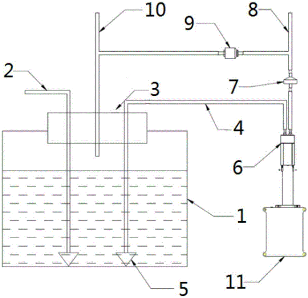
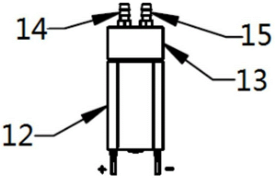
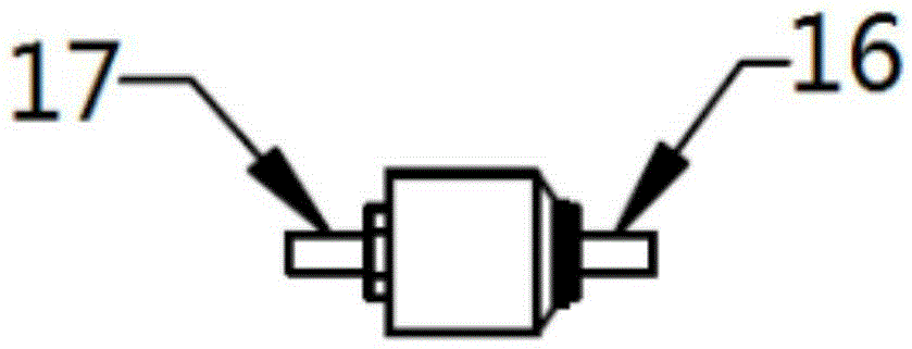
[0017] like Figures 1 to 3 As shown, the small UAV oil supply system provided by the present invention includes a fuel tank 1, a refueling pipe 2, a fuel tank cover 3, an oil suction pipe 4, a weight 5, a micro gear pump 6, a one-way valve 7, a high-pressure oil pipe 8, Micro pressure regulator 9, exhaust pipe 10. The fuel tank cap 3 is provided with a filler port, one end of the fuel filler pipe 2 passes through the fuel filler port of the fuel tank cap 2, and sinks into the bottom of the fuel tank 1 through the weight 5, and the other end of the fuel filler pipe 2 leads to the outside of the fuel tank, except that this end needs to be used when refueling. Plug it up. One end of the oil suction pipe 4 passes through the fuel tank cap 2 and sinks into the bottom of the fuel tank 1 through the weight 5 , and the other end is connected wi...


PUM


Abstract

The invention discloses an engine electric control oil supply device for a model airplane and an unmanned aerial vehicle. The device comprises an oil tank 1, an oiling pipe 2, an oil tank cover 3, an oil sucking pipe 4, a heavy hammer 5, a micro gear pump 6, a one-way valve 7, a high-pressure oil pipe 8, a micro pressure adjuster 9 and an exhaust pipe 10. The oil tank cover is provided with an oiling port, an exhaust port and an oil sucking port. One end of the oiling pipe penetrates through the oiling port of the oil tank cover, and is connected with the heavy hammer to sunk into the bottom of the oil tank; the other end of the oiling pipe is leaded to the external of the oil tank; and the end needs to be blocked by a plug besides of the time of oiling. One end of the oil sucking pipe penetrates through the oil sucking port of the oil tank cover, and is connected with the heavy hammer to sunk into the bottom of the oil tank; and the other end is connected with an oil inlet of the micro gear pump. The micro gear pump drives a gear structure of a main body to generate suction through an internal motor, sucks out fuel in the oil tank through the oil sucking pipe, and provides the fuel with pressure into the high-pressure oil pipe through an oil outlet of the micro gear pump.

Description

technical field [0001] The invention relates to an electronically controlled oil supply device for engines used in model aircraft and unmanned aerial vehicles, in particular to an oil supply device in an electronically controlled fuel injection system for engines used in small aircraft model aircraft or unmanned aerial vehicles. Background technique [0002] At present, the fuel supply system of model airplanes or UAVs generally consists of fuel tanks, oil pipes, carburetors, weights and other components. One end of the oil pipe extending into the fuel tank is connected to the weight, and the other end is directly connected to the oil inlet of the carburetor. The negative pressure generated in the cylinder when the engine is running drives the carburetor diaphragm to pump oil, thus forming a so-called mechanical oil supply system. . But there are multiple defects in such a mechanical oil supply system. First, because air bubbles are likely to be generated in the fuel tank ...

Claims


Application Information

Patent Timeline
Patent Type & Authority Applications(China)
IPC IPC(8): F02M37/08F02M37/00
Inventor 廖明
Owner 石家庄益科创新科技有限公司
Why Eureka
Try Eureka