Positionable overrunning clutch

An overrunning clutch and separation technology, applied in the field of machinery, can solve the problems of increased volume and price, uncertain driven position, etc., and achieve the effect of reducing processing cost and convenient installation.

Active Publication Date: 2017-05-24
BEIJING ABILITY TECH CO LTD
View PDF7 Cites 2 Cited by
  • Summary
  • Abstract
  • Description
  • Claims
  • Application Information

AI Technical Summary

Problems solved by technology

But when the clutch overruns and engages again, the relative angular position of the active and driven devices changes. At this time, although the active device can be accurately positioned, the driven position is already uncertain.
[0004] In order to solve this problem, the traditional method often needs to add an auxiliary positioning system to realize this function, which not only increases the size and price, but also introduces additional potential failure points

Method used


Image

  • Positionable overrunning clutch
  • Positionable overrunning clutch
  • Positionable overrunning clutch

Examples


Embodiment 1

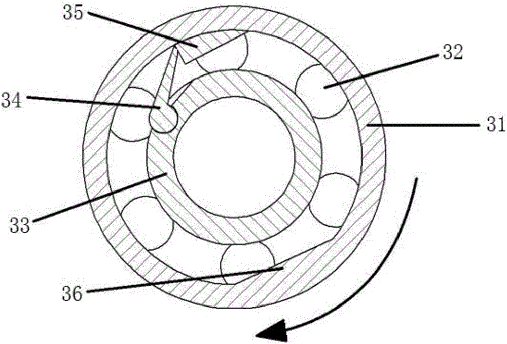
[0045] This embodiment provides a positionable overrunning clutch, which is a typical one-piece type with a structure such as Figure 3A , Figure 3B As shown, it includes an inner ring 33 , an outer ring 31 , a ball 32 , a pawl 34 , a ratchet 35 , a raised weight 36 and a spring 37 . The outer wall of the inner ring 33 contains an inner ring channel 39 along the circumference, and the same height on the inner wall of the outer ring 31 contains a corresponding outer ring channel 38 along the circumference. The balls 32 in the groove are movably connected together. A unique pawl 34 and a unique ratchet 35 are respectively provided on the inner ring 33 and the outer ring 31 .

[0046] The ratchet 34 comprises a pawl tip and a pawl root that is rotatably connected to the inner ring. The position of the pawl root on the inner ring 33 is a cylindrical groove with one side opening, and the opening width is less than the diameter of the cylindrical groove. A cylinder that fits the...

Embodiment 2

[0048]The above embodiment has an integrated structure, but in order to adapt to more installation environments, the clutch can also be a separate structure, which has three types, including the inner ring separated type, the outer ring separated type and the inner ring and outer ring separated type. This embodiment provides a positionable overrunning clutch with a separate inner ring, such as Figure 4 As shown, the structure is generally the same as that of Embodiment 1, the difference is that the inner ring is divided into two parts: the positioning inner ring 42 and the sliding inner ring 44, the pawl and the spring are located on the positioning inner ring 42, and the groove is located on the sliding inner ring 44 superior.

Embodiment 3

[0050] This embodiment provides a positionable overrunning clutch of the outer ring separation type, such as Figure 5 As shown, the structure is generally the same as that of Embodiment 1, the difference is that the outer ring is divided into two parts: the positioning outer ring 52 and the sliding outer ring 51, the ratchet and the protruding weight are located on the positioning outer ring 52, and the grooves are located on the sliding outer ring 52. 51 on the outer ring.


PUM


Abstract

The invention provides a positionable overrunning clutch. The positionable overrunning clutch comprises an outer ring, an inner ring and a plurality of balls for connecting the outer ring with the inner ring; a groove channel is formed in the periphery of the inner side wall of the outer ring, and a corresponding groove channel is formed in the periphery of the outer side wall of the inner ring; the balls are located between the two groove channels and can roll along the groove channels; and one of the inner side wall of the outer ring and the outer side wall of the inner ring is provided with a ratchet, and the other one of the inner side wall of the outer ring and the outer side wall of the inner ring is provided with a pawl capable of being engaged with or separated from the ratchet. According to the positionable overrunning clutch, the relative positions of the inner ring and the outer ring can be fixed, when the system overruns, the performance is not affected, and when the system is engaged, the relative positions of the inner ring and the outer ring are fixed and unchanged.

Description

technical field [0001] The invention relates to the mechanical field, in particular to a positionable overrunning clutch. Background technique [0002] The overrunning clutch is a basic part that appears with the development of mechatronics. It is an important part used for the starting force transmission and separation function between the prime mover and the working machine or between the driving shaft and the driven shaft inside the machine. , The speed change of the driven device or the transformation of the rotation direction is a device with automatic clutch function. figure 1 It is a schematic diagram of a common wedge type one-way overrunning clutch, which includes an outer ring 11 , an inner ring 12 , a wedge 13 and a spring 14 . figure 2 It is a schematic diagram of a common pawl type overrunning clutch, which includes an outer ring 21 , an inner ring 22 and a pawl 23 . [0003] Generally, the overrunning clutch responds quickly and has good versatility, but the...

Claims


Application Information

Patent Timeline
Patent Type & Authority Applications(China)
IPC IPC(8): F16D41/064F16D41/12
CPCF16D41/064F16D41/12F16D2041/0646
Inventor 那星张东明刘玥萌
Owner BEIJING ABILITY TECH CO LTD
Why Eureka
Try Eureka