Speed reducer shell

A technology of reducer and casing, which is applied in the field of reducer casing and casing, which can solve the problems of affecting the service life of the reducer, difficulty in ensuring the sealing effect, and leakage of lubricating oil, so as to achieve broad application prospects and promotion value, and improve the effect of oil leakage prevention , the effect of solving the oil leakage phenomenon

Inactive Publication Date: 2017-05-24
天津市同仁铝压铸件有限公司
View PDF0 Cites 2 Cited by
  • Summary
  • Abstract
  • Description
  • Claims
  • Application Information

AI Technical Summary

Problems solved by technology

[0003] However, because the operating environment of the reducer is usually relatively harsh, during continuous operation, due to the influence of the frictional heat of the moving pair and the ambient temperature, the temperature in the reducer box increases, the pressure gradually increases, and the pressure difference with the outside world also increases. Large, causing the lubricating oil in the box to leak from the gap between the box and the cover due to the pressure difference, which seriously affects the service life of the reducer
To solve this leakage problem, maintenance personnel usually need to disassemble the reducer and replace the deformed and invalid sealing gasket or sealant, which is not only time-consuming and laborious, but also has poor economic benefits, and it is difficult to ensure the sealing effect. Once the oil circuit is formed, it will be used later. Oil leakage will occur again during the process

Method used


Image

  • Speed reducer shell
  • Speed reducer shell
  • Speed reducer shell

Examples


Embodiment Construction

[0019] The present invention will be described in further detail below in conjunction with the accompanying drawings and preferred embodiments.

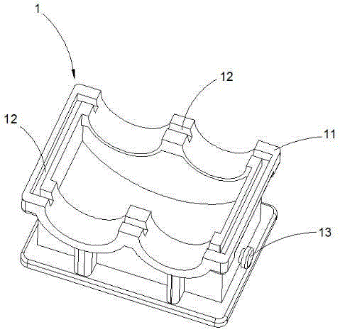
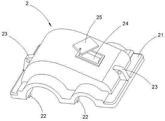
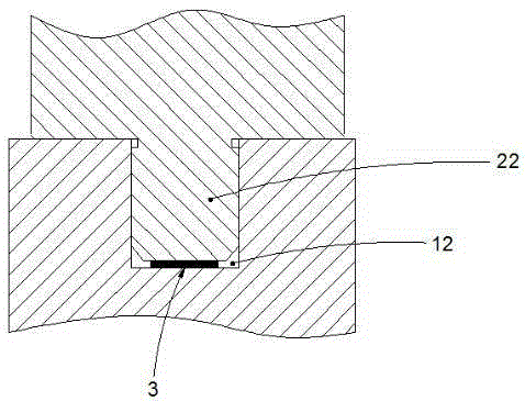
[0020] Figure 1 to Figure 3 , is a schematic diagram of a preferred embodiment of a reducer housing provided by the present invention. Such as Figure 1 to Figure 3 As shown, the material of the reducer shell is cast iron HT200 with good processing performance and excellent shock absorption performance, which specifically includes a box body 1 and a cover body 2. The bottom cover of the cover body 2 is buckled on the top of the box body 1, and the box body 1 A circle of first flanges 11 is provided on the top, a circle of second flanges 21 is provided at the corresponding matching position on the bottom of the cover body 2, a circle of grooves 12 is formed on the first flange 11, and a circle of grooves 12 is formed on the second flange 21. The boss 22 whose shape matches the groove 12, in order to facilitate processing and manufa...


PUM


Abstract

The invention discloses a speed reducer shell, which comprises a box body and a cover body. The bottom part of the cover body is fastened to the top part of the box body in a covering way; a circle of first flange is arranged on the top part of the box body; a circle of second flange is arranged at a corresponding matched position of the bottom part of the cover body; a circle of groove is formed in the first flange; a circle of boss with the shape being matched with the groove is arranged on the second flange; and the cover body is connected with the groove in the first flange through the boss on the second flange in an inserting way. Compared with the prior art, according to the speed reducer shell provided by the invention, a shell structure is reasonably designed, the complexity of an oil circuit at a leakage part is increased, and a sealing gasket is coordinately used for effectively blocking lubricating oil in the groove, so that the oil leakage phenomenon of a bonding surface of the box body and the cover body is prevented, an oil leakage prevention effect is greatly improved, and the service life of a speed reducer is prolonged. Therefore, the speed reducer shell has a wide application prospect.

Description

technical field [0001] The invention relates to a casing, in particular to a reducer casing, which belongs to the technical field of mechanical equipment. Background technique [0002] The reducer is usually used to match the speed and transmit the torque between the prime mover, the working machine or the actuator, and increase the output torque while reducing the speed. It is a relatively precise transmission mechanism and is widely used in the field of modern machinery. . [0003] However, because the operating environment of the reducer is usually relatively harsh, during continuous operation, due to the influence of the frictional heat of the moving pair and the ambient temperature, the temperature in the reducer box increases, the pressure gradually increases, and the pressure difference with the outside world also increases. Large, causing the lubricating oil in the box to leak from the gap between the box and the cover due to the pressure difference, which seriously...

Claims


Application Information

Patent Timeline
Patent Type & Authority Applications(China)
IPC IPC(8): F16H57/02F16H57/032F16H57/029
CPCF16H57/02F16H57/029F16H57/032
Inventor 刘哲学
Owner 天津市同仁铝压铸件有限公司
Why Eureka
Try Eureka