Improved Furnace Core for Compression Combustion Furnace

A combustion furnace, an improved technology, applied in burners, combustion equipment, combustion using liquid fuels and gaseous fuels, etc. Stable, easy to clean, smooth air intake

Active Publication Date: 2019-05-17
肇庆市高要区鼎星五金实业有限公司
View PDF1 Cites 0 Cited by
  • Summary
  • Abstract
  • Description
  • Claims
  • Application Information

AI Technical Summary

Problems solved by technology

[0003] The air intake holes of existing compression combustion furnaces, i.e. wind eyes, are prone to rust and blockage, while in traditional combustion furnaces, the air holes are usually set on the side wall of the furnace core body, and the furnace core body is usually connected to the shell of the combustion furnace The body is fixed and assembled as a whole, and it is not easy to take it up for cleaning. Therefore, when the wind eye is blocked, the fuel in the combustion furnace is not fully burned, the energy utilization rate is low, and the noise is large.
For example, in the invention patent with the application number CN201410791384.3 and the name "Low-noise and energy-saving furnace core for compression combustion furnace", the first air inlet located in the combustion pool is easy to rust and block and is not easy to clean, thereby affecting The use effect of the product, and even affect the service life of the product

Method used


Image

  • Improved Furnace Core for Compression Combustion Furnace
  • Improved Furnace Core for Compression Combustion Furnace
  • Improved Furnace Core for Compression Combustion Furnace

Examples


Embodiment Construction

[0036] In order to further explain the technical solution of the present invention, the present invention will be described in detail below through specific examples.

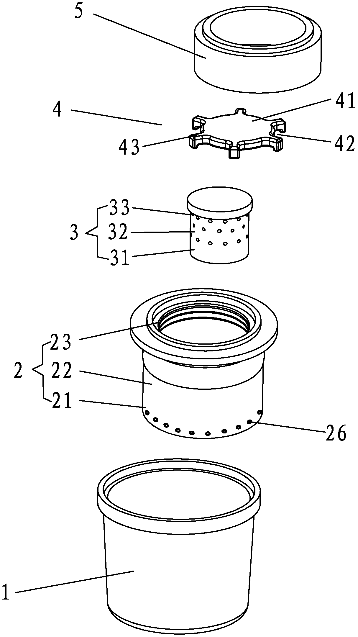
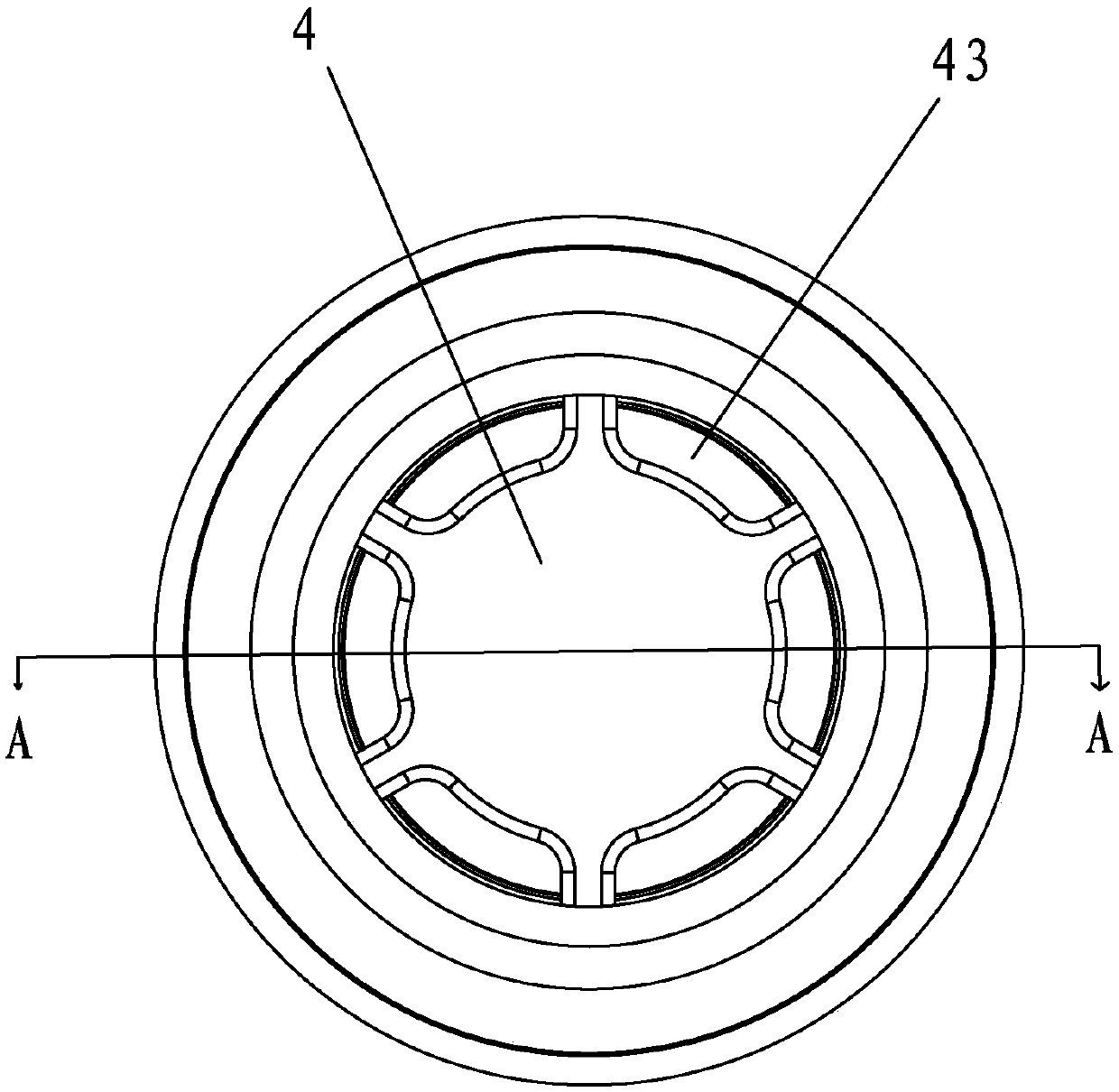
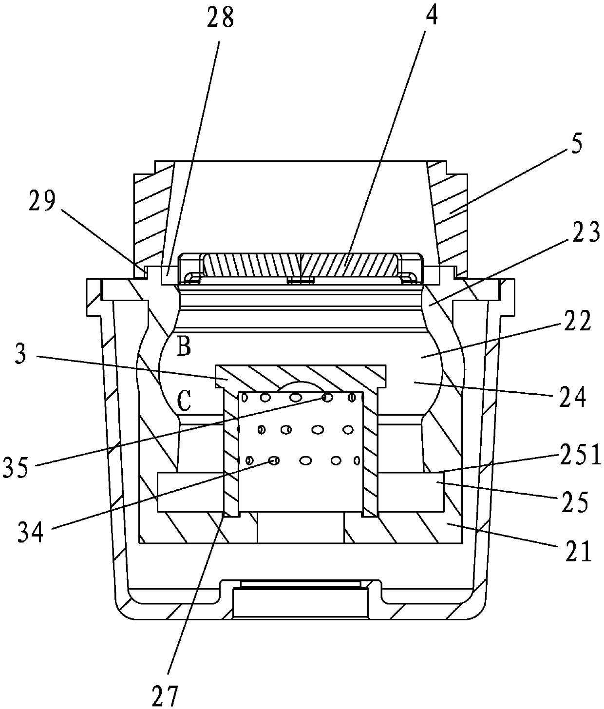
[0037] An improved core for a compression combustion furnace having a core body such as Figure 1-3 As shown, the main body of the furnace core includes an outer casing 1 , a main casing 2 , a wind control cylinder 3 , a gasification cover 4 and a fire stabilization ring 5 . The outer casing 1 is sleeved outside the main casing 2, the wind control cylinder 3 is installed in the main casing 2, the gasification cover 4 is sealed at the opening of the main casing 2, and the fire stabilization ring 5 is installed in the main casing On the open end of the body 2, the adjustment makes the flame burned out by the combustion furnace more stable and concentrated, and the energy utilization rate is improved.

[0038] by image 3 The orientation shown is a reference orientation, and the inside of the main housing 2 is a...


PUM


Abstract

The invention discloses an improved type furnace core for a compressed type burning furnace. The improved type furnace core comprises a main shell and an air controlling pillar body installed in the main shell; the air controlling pillar body comprises an opening closing section, a middle section and an opening section which are sequentially connected, and the main shell comprises an opening closing section, a middle section and an opening section which are sequentially connected; and a plural number of first air holes which incline in the same direction are formed in the side wall of the middle section of the air controlling pillar body, a plural number of second air holes which incline in the direction opposite to the first air holes are formed in the side wall of the opening closing section of the air controlling pillar body, and the opening closing section of the main shell is covered with a gasification cap in a closed mode. According to the improved type furnace core for the compressed type burning furnace, after a structure is adopted, the first air holes and the second air holes are formed in the side wall of the air controlling pillar body, and through wind power burning supporting, normal burning use of the furnace core is ensured; the air controlling pillar body can be directly placed in the main shell, taking and bringing are convenient, and although the air holes of the air controlling pillar body are blocked, clearing is also easily conducted; and the gasification cap contributes to compressing burning, so that fuel burning is more sufficient, burned-out flames are more stable, and occurrence of the arcing phenomenon of a traditional burning furnace is avoided.

Description

technical field [0001] The present invention relates to a component used in a compression combustion furnace, in particular to an improved furnace core for a compression combustion furnace. Background technique [0002] The compression combustion furnace is a kind of tube heating furnace. It blows air into the combustion pool through a fan or a compressor, ignites the fuel through an igniter, and pushes the flame out quickly under the agitation of the air. [0003] The air intake holes of existing compression combustion furnaces, i.e. wind eyes, are prone to rust and blockage, while in traditional combustion furnaces, the air holes are usually set on the side wall of the furnace core body, and the furnace core body is usually connected to the shell of the combustion furnace The body is fixed and assembled as a whole, and it is not easy to take it up for cleaning. Therefore, when the wind eye is blocked, the fuel in the combustion furnace is not fully burned, the energy utili...

Claims


Application Information

Patent Timeline
Patent Type & Authority Patents(China)
IPC IPC(8): F23C1/08F23C7/00F23D11/36F23D17/00
CPCF23C1/08F23C7/00F23D11/36F23D17/002
Inventor 洪序明
Owner 肇庆市高要区鼎星五金实业有限公司
Why Eureka
Try Eureka