Device for simulating boundary condition of simple support during plate piece testing

A boundary condition and plate technology, which is applied in the field of simply supported boundary conditions in the simulated plate test, can solve the problems of failure to achieve the test purpose, complex structure, unsuitable curved plate structure, etc., and achieve strong design and production feasibility , Accurate installation position and compact structure

Pending Publication Date: 2017-05-24
RAILWAY ENG RES INST CHINA ACADEMY OF RAILWAY SCI +1
View PDF7 Cites 7 Cited by
  • Summary
  • Abstract
  • Description
  • Claims
  • Application Information

AI Technical Summary

Problems solved by technology

At present, when carrying out static load or stability tests of plates at home and abroad, the lower end of the test piece is generally set as a hinge, and the upper end is loaded. There are three ways to deal with the boundary conditions on both sides of the plate. The first is to directly make it Free, without imposing any constraints, this treatment method is quite different from the actual structure. During the test, the free edge of the plate will be unstable first, so that the purpose of the test cannot be achieved; the second is to use multi-point constraints, that is, the plate The screw is used to compress the plate at a certain distance on both sides. This treatment method is also inconsistent with the actual structure, and it is difficult to control the preload of different screw to be the same, and it is not suitable for the curved plate structure; the third is to use The clamps with blades clamp the two sides of the specimen. Although this treatment method is consistent with the actual structure, the structure is complicated, the positioning of the plate is difficult, and it is not suitable for the curved plate structure.

Method used


Image

  • Device for simulating boundary condition of simple support during plate piece testing
  • Device for simulating boundary condition of simple support during plate piece testing
  • Device for simulating boundary condition of simple support during plate piece testing

Examples


Embodiment Construction

[0039] In order to make the object, technical solution and advantages of the present invention clearer, the present invention will be further described in detail below in conjunction with the accompanying drawings and embodiments. It should be understood that the specific embodiments described here are only used to explain the present invention, not to limit the present invention.

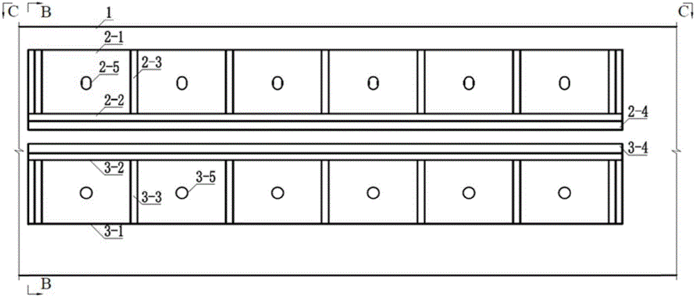
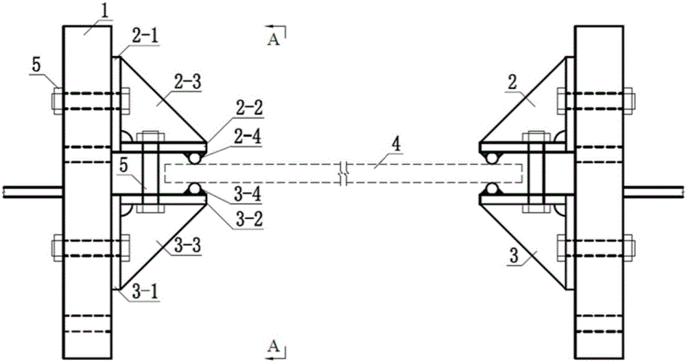
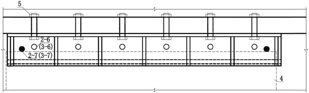
[0040] A device for simulating simply supported boundary conditions in plate tests, such as Figure 2b shown, including:

[0041] Fixing device 1 on both sides, which can be an integral steel frame or a reinforced concrete structure with pre-embedded connecting steel plates, including two bracket steel plates, the two bracket steel plates are parallel to each other and placed vertically, and are respectively fixed along the upper and lower sides of each bracket steel plate There are upper fixture 2 and lower fixture 3;

[0042] The upper fixture 2 includes an upper vertical plate 21 and an upper ...


PUM


Abstract

The invention relates to a device for simulating a boundary condition of a simple support during plate piece testing. Upper fixtures and lower fixtures are fixed above and below a bilateral fixing device; the upper fixtures comprise upper vertical plates and upper horizontal plates that are welded into right angles; a plurality of parallel upper stiffening plates are welded in the right angles and are in welded connection with the upper vertical plates and the upper horizontal plates; upper round steel bars are welded on the lower surfaces of the upper horizontal plates; the lower fixtures comprise lower vertical plates and lower horizontal plates that are welded into right angles; a plurality of parallel lower stiffening plates are welded in the right angles and are in welded connection with the lower vertical plates and the lower horizontal plates; lower round steel bars are welded on the upper planes of the lower horizontal plates; and a plate piece is placed between the upper horizontal plates and the lower horizontal plates and inserted between the upper round steel bars and the lower round steel bars. The device is wide in application scope, and is applicable to testing of both specimens with different plate thicknesses and bent plate specimens.

Description

technical field [0001] The invention relates to a device for simulating simply supported boundary conditions in plate tests. Background technique [0002] The slab structure is a commonly used structural form of engineering structures, which can bear both out-of-plane loads and in-plane loads. When the plate is subjected to out-of-plane load or in-plane tensile load, when the load reaches a certain level, the surface fiber stress exceeds the ultimate tensile strength of the material, and the plate will suffer tensile failure; when the plate is subjected to in-plane compressive load, a situation If the width-thickness ratio of the board is small, when the load is added to the surface fiber stress to reach the ultimate compressive strength of the material, the board will be compressed and damaged; in another case, the width-thickness ratio of the board is large, when the load is added to a certain level, the surface fiber stress has not yet reached When the ultimate compressi...

Claims


Application Information

Patent Timeline
Patent Type & Authority Applications(China)
IPC IPC(8): G01N3/04
CPCG01N3/04G01N2203/04G01N2203/0282
Inventor 曾志斌史志强方兴郭辉
Owner RAILWAY ENG RES INST CHINA ACADEMY OF RAILWAY SCI
Why Eureka
Try Eureka