Flexible tunneling machine for installing sleeve

A technology of telescopic casing and roadheader, which is applied in drilling equipment, drilling equipment and methods, earthwork drilling and production, etc., and can solve the problems of failure of casing ramming, high degree of sinking at the end of casing, difficulty in tamping casing, etc. problem, to achieve the effect of no jamming, small deformation, and simple and reliable recycling scheme

Active Publication Date: 2012-07-18
BC P INC CHINA NAT PETROLEUM CORP +1
View PDF5 Cites 7 Cited by
  • Summary
  • Abstract
  • Description
  • Claims
  • Application Information

AI Technical Summary

Problems solved by technology

[0003] In order to solve the problems that the ramming casing is not easy to be in place during the traditional horizontal directional drilling penetration, the casing end has a large sinking degree, and the casing fails to be rammed under high water pressure. The present invention provides a telescopic casing installation roadheader, including Retractable cutter head, cutter head support plate, cone crushing device, front housing, fixing device, power system, rear housing, oil cylinder, recovery system, inlet and discharge mud pipes, mud nozzles and cutter head positioning pins; The telescopic cutterhead is connected to the cutterhead support plate through the cutterhead positioning pin, the retractable cutterhead is connected to the rotating main shaft of the cone crushing device, and the rotating main shaft of the cone crushing device is connected to the main shaft of the power system , the cone-shaped crushing device is welded in the front shell, the recovery system is installed at the tail of the rear shell, and the oil cylinder is installed on the front shell and the rear shell through a fixing seat; the The fixing device is used to fix the telescopic casing to install the roadheader and the steel casing to be installed; the inlet and discharge mud pipes are fixed below the inside of the rear casing for pumping mud and discharging cuttings; the mud nozzle Circumferentially arranged above the cone crushing device and facing the inner cavity

Method used


Image

  • Flexible tunneling machine for installing sleeve
  • Flexible tunneling machine for installing sleeve
  • Flexible tunneling machine for installing sleeve

Examples


Embodiment Construction

[0012] The technical solutions of the present invention will be further described below in conjunction with the accompanying drawings and embodiments.

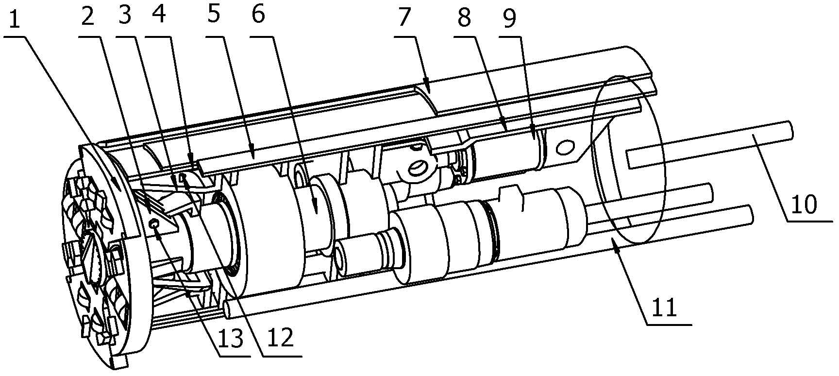
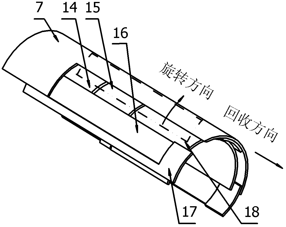
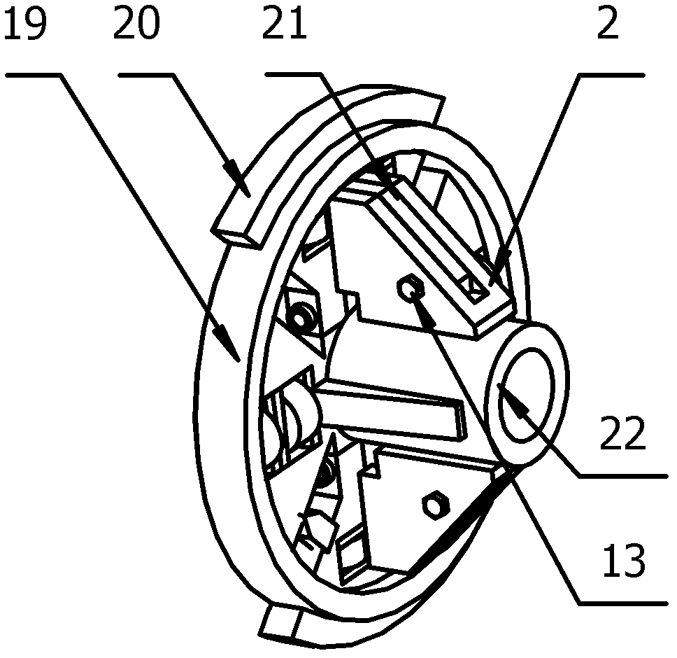
[0013] The embodiment of the present invention adopts the principles of mechanical cutting, cutter head opening and closing shrinkage recovery and muddy water transportation to discharge slag, and develops a mechanical equipment for horizontal directional drilling to penetrate sand layers and gravel installation casings, and can be taken out from the casing as a whole , can be used for overall recovery of the machine head, removal of obstacles or replacement of tools during pipe jacking under complex geological conditions.

[0014] Such as figure 1 As shown, the embodiment of the present invention provides a telescopic casing installation tunneling machine, including a telescopic cutter head 1, a cutter head support plate 2, a cone crushing device 3, a front housing 4, a fixing device 5, and a power system 6 , rear housing 8,...


PUM


Abstract

The invention discloses a flexible tunneling machine for installing a sleeve, belonging to the technical field of underground oil-gas reservoir exploitation. The tunneling machine comprises a flexible cutter head, a cutter head supporting plate, a conical crushing device, a front shell, a fixing device, a dynamic system, a rear shell, oil cylinders, a recovery system, a slurry inlet/outlet pipe, a slurry nozzle and a cutter head positioning pin, wherein the flexible cutter head is connected with the cutter head supporting plate through the cutter head positioning pin; the flexible cutter head is connected with a rotary main shaft of the conical crushing device; the rotary main shaft of the conical crushing device is connected with the main shaft of the dynamic system; the conical crushing device is welded in the front shell; the recovery system is arranged at the tail part of the rear shell; the oil cylinders are arranged on the front shell and the rear shell through fixing seats; the slurry inlet/outlet pipe is fixed below the inner part of the rear shell; and the slurry nozzle is arranged on the conical crushing device. The flexible tunneling machine for installing the sleeve is reasonable in structural design, correct and efficient in steel sleeve mounting position, free of end part sinking phenomenon, simple and reliable in recovery scheme and free of clamping phenomenon.

Description

technical field [0001] The invention relates to the technical field of exploitation of underground oil and gas reservoirs, in particular to a tunneling machine for installing telescopic sleeves. Background technique [0002] When traditional horizontal directional drilling passes through sand layers, pebbles and gravel layers and other difficult-to-pore formations, the process of isolating pebbles and gravels by using a rammer to ram the casing is used. However, this method is not suitable for all geological types, and various problems often occur in practical applications, mainly in the following aspects: (1) Casing tamping is not in place, for example, the horizontal directional drilling of a river crosses the casing design distance 150 meters, actually only rammed into 50 meters, resulting in the failure of directional drilling for construction, and changing to large excavation; (2) The sinking degree of the end of the casing is as high as 4°, resulting in changes in the ...

Claims


Application Information

Patent Timeline
Patent Type & Authority Applications(China)
IPC IPC(8): E21B7/20
Inventor 张宝强袁春孙玉高刘艳利王磊张倩江勇焦如义韩涛
Owner BC P INC CHINA NAT PETROLEUM CORP
Why Eureka
Try Eureka