Mutual coupling correction-based radar array adaptive beamforming method

A technology of adaptive beam and radar array, applied in the design of adaptive beamformer, the field of adaptive beamforming of radar array, can solve the problems such as the performance of adaptive beamformer is particularly significant, the performance of beamformer is degraded, deviation and so on , to achieve the effect of good target detection performance

Active Publication Date: 2017-05-24
XIDIAN UNIV
View PDF10 Cites 8 Cited by
  • Summary
  • Abstract
  • Description
  • Claims
  • Application Information

AI Technical Summary

Problems solved by technology

[0004] Although the traditional beamforming method can form a high gain in the required direction, it does not have the function of suppressing the interference signal; in the 1960s, the minimum variance distortion-free response (MVDR) beamformer proposed by Capon was deduced through the theory The method of calculating array adaptive weights based on the interference-plus-noise covariance matrix above can form a response null in the interference direction while ensuring the gain of the signal in the desired direction. In theory, the interference signal can be effectively suppressed, and the subsequent The sampled matrix inversion (SMI) beamformer, which uses the received signal sampling covariance matrix instead of the theoretical interference plus noise covariance matrix, can adaptively suppress interference according to the received signal of the array antenna, and is a classic adaptive beamformer.
[0005] The classic sampled matrix inversion (SMI) beamformer can adaptively suppress the interference signal and ensure the detection performance of the desired signal in theory, but in practical applications, due to the influence of factors such as the mutual coupling effect between the array antenna elements , there is a large deviation between the actual steering vector of the desired signal and the ideal steering vector assumed in the algorithm, and applying the traditional adaptive beamforming algorithm to an uncalibrated array antenna will lead to a serious decline in the performance of the beamformer; The mutual coupling effect, one of the most influential factors of the steering vector deviation of the signal, has a particularly significant impact on the performance of the adaptive beamformer

Method used


Image

  • Mutual coupling correction-based radar array adaptive beamforming method
  • Mutual coupling correction-based radar array adaptive beamforming method
  • Mutual coupling correction-based radar array adaptive beamforming method

Examples


Embodiment Construction

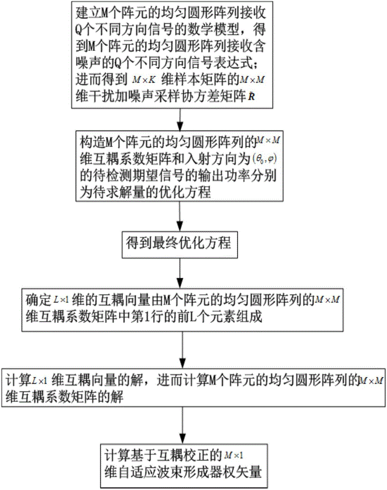
[0034] refer to figure 1 , is a flow chart of a radar array adaptive beamforming method based on mutual coupling correction in the present invention; the radar array adaptive beamforming method based on mutual coupling correction includes the following steps:

[0035] Step 1. Establish a mathematical model for a uniform circular array of M array elements to receive signals in Q different directions, where there are mutual coupling effects and array element amplitude and phase errors between M array elements; In the case of mutual coupling effects and array element amplitude and phase errors, the echo signal received by a uniform circular array of M array elements at time t from the radar array is expressed as X(t), X(t)=CAS(t)+ N(t), where C is the M×M dimensional mutual coupling coefficient matrix of a uniform circular array of M array elements, which means that when considering the mutual coupling effect between array elements in a uniform circular array of M array elements,...


PUM


Abstract

The invention discloses a mutual coupling correction-based radar array adaptive beamforming method. The method includes the following steps that: a mathematical model of the receiving of Q different direction signals by a uniform circular array of M array elements is established, an expression X<^>(t) of the receiving of Q different direction signals containing noises by the uniform circular array of M array elements and K received signal samples are obtained, and an interference and noise sampling covariance matrix R <~> of a sample matrix XK is calculated; the output power Pout (theta0, phi) of desired signals to be detected of which the incident direction is (theta0, phi) is calculated, C is constructed, and C and the output power Pout (theta0, phi) of the desired signals to be detected of which the incident direction is (theta0, phi) are adopted as optimization equations of a quantity to be solved, and a final optimization equation is obtained; it is determined that the product of C and the ideal steering vector alpha (theta0, phi) of the desired signals to be detected of which the incident direction is (theta0, phi) is equivalent to the product of an M*L-dimensional matrix T corresponding to M elements included in the alpha (theta0, phi) and a mutual coupling vector, and it is determined that the mutual coupling vector is composed of the first L elements in the first row in C; and the solution of c and the solution of C are calculated; and an optimization function is constructed, and a mutual coupling correction-based adaptive beamformer weight vector is calculated.

Description

technical field [0001] The invention belongs to the technical field of array signal processing, in particular to a radar array adaptive beamforming method based on mutual coupling correction, which is suitable for self-adaptation under the mutual coupling effect between sensors in a uniform circular array antenna in a radar or communication system Beamformer Design. Background technique [0002] Array signal processing has a wide range of applications in communication, radar, sonar, electronic countermeasures, medical imaging, radio astronomy and other fields. Beamforming technology is an important branch of array signal processing; as phased array antennas are used in radar and communication systems With the popularization of the beamforming technology and methods, the beamforming technology and methods have also been rapidly developed and improved. The original beamforming technology applies different feed phases to different array sensors so that the output phase of the c...

Claims


Application Information

Patent Timeline
Patent Type & Authority Applications(China)
IPC IPC(8): G01S7/36
CPCG01S7/36
Inventor 王彤李博文刘程
Owner XIDIAN UNIV
Why Eureka
Try Eureka