Machine vision lens

A machine vision and lens technology, applied in the direction of instruments, optical components, optics, etc., can solve problems such as the inability to meet the low distortion effect, the inability to solve the temperature drift, the inability to meet the needs of users, etc., to solve the problem of poor high and low temperature resolution, and achieve heat dissipation. Aberration and chromatic aberration, the effect of solving special problems of optical distortion

Active Publication Date: 2017-05-24
舜宇光学(中山)有限公司
View PDF5 Cites 15 Cited by
  • Summary
  • Abstract
  • Description
  • Claims
  • Application Information

AI Technical Summary

Problems solved by technology

Once the information is seriously lost in the imaging system, it is very difficult to try to recover it later
[0003] Traditional machine vision lenses cannot meet the low distortion effect or maintain clear imaging in a wide temperature range, cannot solve the problem of temperature drift, and cannot meet user needs

Method used


Image

  • Machine vision lens
  • Machine vision lens
  • Machine vision lens

Examples


no. 1 example

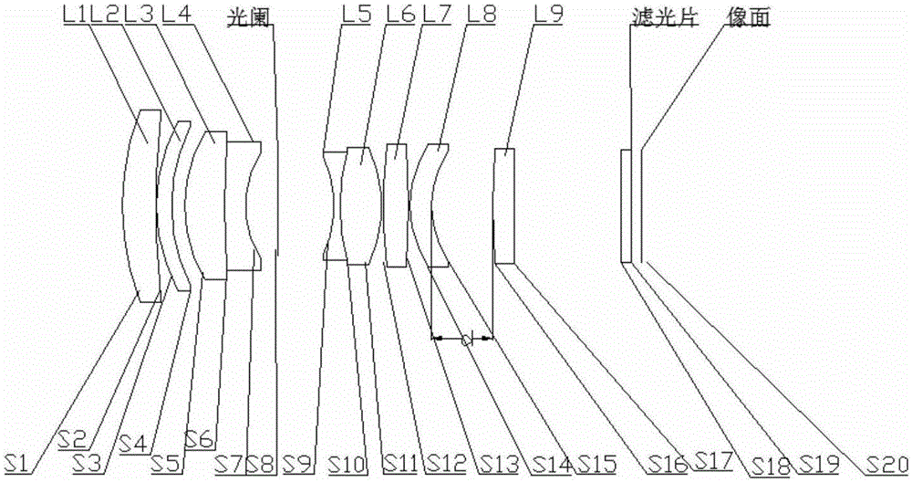
[0055] see Figure 1-Figure 7 , the machine vision lens includes a focusing group, a diaphragm and a fixed group in sequence from the object side to the image side, and the focusing group includes a first lens L1 with positive refractive power, a second lens L2 with positive refractive power, Third lens L3 with positive power and fourth lens L4 with negative power, fifth lens L5 with negative power, sixth lens L6 with positive power, seventh lens with positive power L7, an eighth lens L8 with negative power; the fixed group includes a ninth lens L9 with positive power.

[0056] In this embodiment, the first lens L1 is a concave-convex structure that bends toward the image plane; the focal length of the first lens L1 is fL1; the second lens L2 is a concave-convex structure that bends toward the image plane; the focal length of the second lens L2 is fL2; The third lens L3 is a concave-convex structure that bends toward the image surface; the focal length of the third lens L3 is...

no. 2 example

[0081] see Figure 8-Figure 13 , in the present embodiment, when the focal length of the 9 lenses of the visual lens and a piece of protective glass, the group air interval d and the radius of curvature of the lens, thickness, spacing, refractive index, and Abbe number meet the following conditions respectively:

[0082] WD=600mm, f=33.4mm, F#=2.02, FOV=18.3°;

[0083] fL1 f2 f3 f4 f5 f6 f7 f8 wxya 44.43 341.50 27.18 -14.08 -19.32 19.70 42.14 -383.83 96.28

[0084] |f1 / f2| |fB1 / fB2| fL1 / f1 fL2 / f1 fL7 / f2 fL8 / f2 0.397 0.132 1.163 8.942 0.438 -3.987

[0085] Object distance(mm) infinity 1000 600 200 100 d 2.319 3.817 4.855 10.559 21.272

[0086]

[0087] In the above table, "n" is the refractive index, "R" is the radius of curvature, fL1~fL9 are the focal lengths of each lens, f1 is the focal length of the focusing group, f2 is the focal length of the fixed group, and fB1 ...

no. 3 example

[0091] see Figure 14-Figure 19 , in the present embodiment, when the focal length of the 9 lenses of the visual lens and a piece of protective glass, the group air interval d and the radius of curvature of the lens, thickness, spacing, refractive index, and Abbe number meet the following conditions respectively:

[0092] WD=600mm, f=35mm, F#=2.04, FOV=17.6°.

[0093] fL1 f2 f3 f4 f5 f6 f7 f8 wxya 46.41 305.05 28.01 -14.01 -21.61 21.03 33.26 -87.62 83.03

[0094] |f1 / f2| |fB1 / fB2| fL1 / f1 fL2 / f1 fL7 / f2 fL8 / f2 0.490 0.176 1.141 7.502 0.401 -1.055

[0095] Object distance(mm) infinity 1000 600 200 100 d 3.033 4.734 5.910 12.402 24.582

[0096]

[0097]

[0098] In the table, "n" is the refractive index, "R" is the radius of curvature, fL1~fL9 are the focal lengths of each lens, f1 is the focal length of the focusing group, f2 is the focal length of the fixed group, and ...


PUM


Abstract

The invention relates to a machine vision lens, which successively comprises a focusing group, a diaphragm and a fixed group from an object side to an image side, wherein the focusing group comprises a first lens with positive focal power, a second lens with positive focal power, a third lens with positive focal power, a fourth lens with negative focal power, a fifth lens with negative focal power, a sixth lens with positive focal power, a seventh lens with positive focal power and an eighth lens with negative focal power; the fixed group comprises a ninth lens with positive focal power; the focusing group has positive focal power, the focal length of the focusing group is f1, the fixed group has negative focal power, the focal length of the fixed group is f2, wherein an absolute value of (f1 / f2) is greater than 0.35 and less than 0.5. The machine vision lens adopts a rear group fixing focusing structure, so that low distortion performance can be realized in a working distance from the infinity to an ultra-near shooting distance. The machine vision lens has a characteristic that high resolution of images is maintained in a wide temperature range.

Description

technical field [0001] The invention relates to a machine vision lens and relates to the field of optical equipment. Background technique [0002] Machine vision is the use of machines instead of human eyes for measurement and judgment. The machine vision system refers to converting the target to be detected into a digital signal through a machine vision product (that is, an image capture device, which is divided into two types: CMOS and CCD), and these digital signals are then sent to a dedicated image processing system (divided into embedded and video) card mode), the image processing system sets the detection task according to the requirements of the target to be detected. Then according to the result of the discrimination, it controls the action of the on-site equipment to realize the functions of positioning, judgment, identification, detection and control. Once the information is seriously lost in the imaging system, it is very difficult to try to recover it in the f...

Claims


Application Information

Patent Timeline
Patent Type & Authority Applications(China)
IPC IPC(8): G02B15/16G02B1/00
CPCG02B15/16G02B1/00
Inventor 蓝岚付湘发高屹东梁伟朝白兴安贺保丁张鸿佳周静张德伦
Owner 舜宇光学(中山)有限公司
Why Eureka
Try Eureka