machine vision lens
A machine vision and lens technology, applied in instruments, optical components, optics, etc., can solve problems such as inability to meet low distortion effects, inability to solve temperature drift, inability to meet user needs, etc. Aberration and chromatic aberration, the effect of solving special problems of optical distortion
- Summary
- Abstract
- Description
- Claims
- Application Information
AI Technical Summary
Problems solved by technology
Method used
Image
Examples
no. 1 example
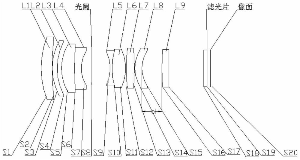
[0055] see Figure 1-Figure 7 , This machine vision lens, from the object side to the image side, includes a focusing group, a diaphragm and a fixed group in order, and the focusing group includes a first lens L1 with positive refractive power, a second lens with positive refractive power L2, The third lens L3 having positive refractive power, the fourth lens L4 having negative refractive power, the fifth lens L5 having negative refractive power, the sixth lens L6 having positive refractive power, the seventh lens having positive refractive power L7, the eighth lens L8 with negative refractive power; the fixed group includes the ninth lens L9 with positive refractive power.
[0056] In this embodiment, the first lens L1 is a concave-convex structure curved toward the image plane; the focal length of the first lens L1 is fL1; the second lens L2 is a concave-convex structure curved toward the image plane; the focal length of the second lens L2 is fL2; The third lens L3 is a con...
no. 2 example
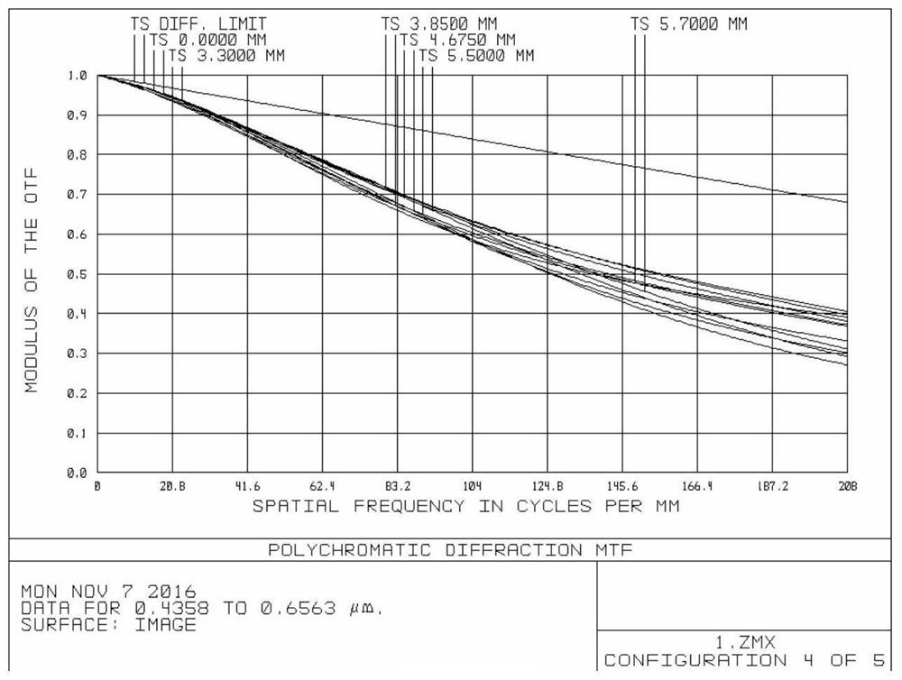
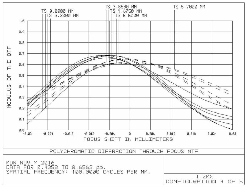
[0081] see Figure 8-Figure 13 , in the present embodiment, when the focal length, group air interval d and lens curvature radius, thickness, spacing, refractive index, and Abbe number of 9 lenses and a protective glass of the visual lens satisfy the following conditions respectively:
[0082] WD=600mm, f=33.4mm, F#=2.02, FOV=18.3°;
[0083] fL1 fL2 fL3 fL4 fL5 fL6 fL7 fL8 fL9 44.43 341.50 27.18 -14.08 -19.32 19.70 42.14 -383.83 96.28
[0084] |f1 / f2| |fB1 / fB2| fL1 / f1 fL2 / f1 fL7 / f2 fL8 / f2 0.397 0.132 1.163 8.942 0.438 -3.987
[0085] Object distance (mm) infinity 1000 600 200 100 d 2.319 3.817 4.855 10.559 21.272
[0086]
[0087] In the above table, "n" is the refractive index, "R" is the radius of curvature, fL1~fL9 are the focal lengths of each lens, f1 is the focal length of the focusing group, f2 is the focal length of the fixed group, and fB1 and fB2 are the focal...
no. 3 example
[0091] see Figure 14-Figure 19 , in the present embodiment, when the focal length, group air interval d and lens curvature radius, thickness, spacing, refractive index, and Abbe number of 9 lenses and a protective glass of the visual lens satisfy the following conditions respectively:
[0092] WD=600mm, f=35mm, F#=2.04, FOV=17.6°.
[0093] fL1 fL2 fL3 fL4 fL5 fL6 fL7 fL8 fL9 46.41 305.05 28.01 -14.01 -21.61 21.03 33.26 -87.62 83.03
[0094] |f1 / f2| |fB1 / fB2| fL1 / f1 fL2 / f1 fL7 / f2 fL8 / f2 0.490 0.176 1.141 7.502 0.401 -1.055
[0095] Object distance (mm) infinity 1000 600 200 100 d 3.033 4.734 5.910 12.402 24.582
[0096]
[0097]
[0098] In the table, "n" is the refractive index, "R" is the radius of curvature, fL1~fL9 are the focal lengths of each lens, f1 is the focal length of the focusing group, f2 is the focal length of the fixed group, and fB1 and fB2 are the f...
PUM
 Abstract
Description
Claims
Application Information
 - R&D
- Intellectual Property
- Life Sciences
- Materials
- Tech Scout
- Unparalleled Data Quality
- Higher Quality Content
- 60% Fewer Hallucinations
Browse by: Latest US Patents, China's latest patents, Technical Efficacy Thesaurus, Application Domain, Technology Topic, Popular Technical Reports.
© 2025 PatSnap. All rights reserved.Legal|Privacy policy|Modern Slavery Act Transparency Statement|Sitemap|About US| Contact US: help@patsnap.com


