
Coaxial four-mirror catadioptric low-distortion telescopic optical system

An optical system, catadioptric technology, applied in optics, telescopes, optical components, etc., can solve the problem that it is difficult to meet the future development needs of high-precision surveying and mapping cameras, difficult to process and assemble off-axis three-mirror systems, and difficult to implement systems sensitive engineering, etc. problems, to achieve low-distortion space imaging, improve transfer and imaging performance, and suppress off-axis field of view stray light.

Active Publication Date: 2020-05-08
SHANGHAI INST OF TECHNICAL PHYSICS - CHINESE ACAD OF SCI
View PDF9 Cites 6 Cited by
  • Summary
  • Abstract
  • Description
  • Claims
  • Application Information

AI Technical Summary

Problems solved by technology

Due to the limitation of the material size of the transmission optical system, it is not suitable for surveying and mapping cameras with long focal length and large aperture; while the processing and assembly of the off-axis three-mirror system are extremely difficult, the distortion in the meridional direction is difficult to control, and the sensitivity of the system makes engineering implementation difficult. Difficult to guarantee; the coaxial three-mirror optical system project in orbit, its optical distortion reaches the order of a few percent, and the absolute distortion brings great difficulties to the later data processing and correction, and it is difficult to meet the requirements of high-precision surveying and mapping cameras. future development needs

Method used


Image

  • Coaxial four-mirror catadioptric low-distortion telescopic optical system
  • Coaxial four-mirror catadioptric low-distortion telescopic optical system
  • Coaxial four-mirror catadioptric low-distortion telescopic optical system

Examples


Embodiment Construction

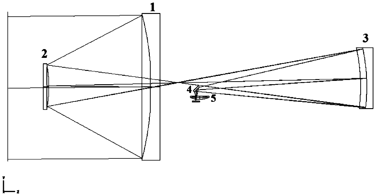
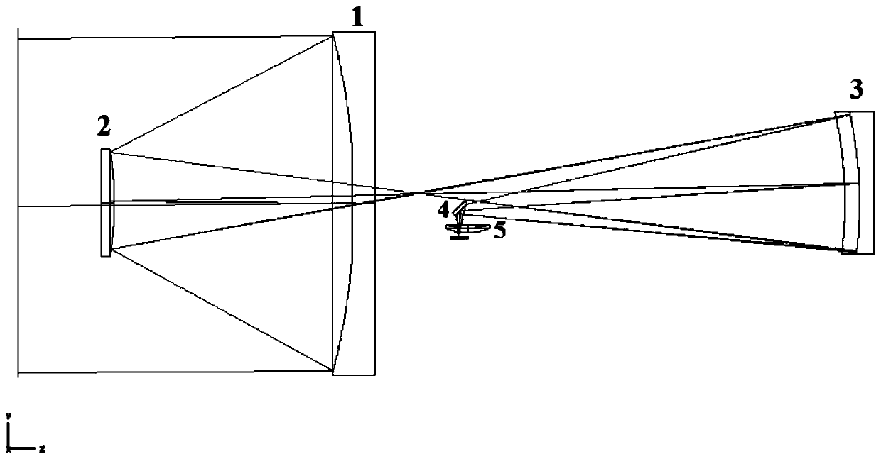
[0017] The present invention designs a coaxial four-mirror catadioptric low-distortion telescopic optical system, the main technical features of which are as follows:

[0018] 1. Caliber: aperture stop 500mm;

[0019] 2. Field of view: 1.5°;

[0020] 3. Working band: 400nm-800nm;

[0021] 4. Relative aperture: 1 / 3, focal length 1500mm;

[0022] 5. Detector parameters: pixel size 5μm, pixel number 8K×2;

[0023] 6. Spatial resolution: better than 3.3μrad;

[0024] 7. Distortion: ≤ two millionths;

[0025] 7. Imaging performance: The full-field transmission is better than 0.55 at the Nyquist frequency of 100lp / mm, and the full-field distortion is less than 1 micron.

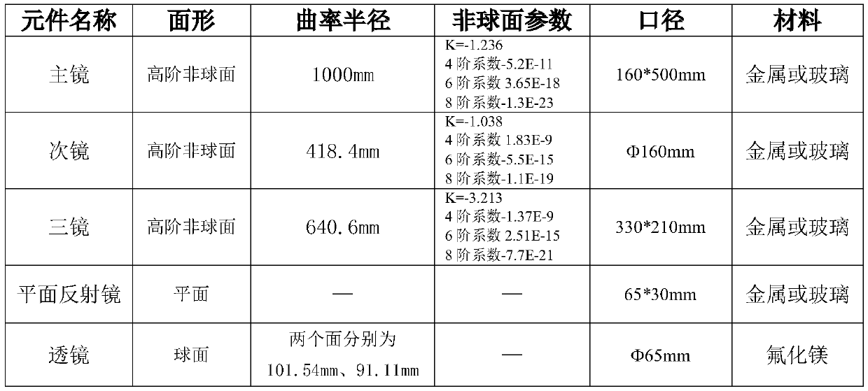
[0026] Table 1 Specific design parameters of the optical system

[0027]


PUM


Abstract

The invention discloses a coaxial four-mirror catadioptric low-distortion telescopic optical system, which is characterized in that an off-axis light beam of a target scene is reflected by a primary mirror, a secondary mirror, a third mirror and a plane mirror and then is transmitted and converged to a focal plane detector through a lens, and the optical axes of all mirror surfaces are on the samestraight line; and the plane mirror is located between the primary mirror and the third mirror. The primary mirror and the secondary mirror form a Cassegrain system to form a primary real image, andthe primary real image is imaged on the focal plane detector through the third mirror, the plane mirror and the lens relay; the primary mirror, the secondary mirror and the third mirror bear most of focal power, and the lens bears small focal power and is used for correcting distortion. The aperture diaphragm is located on the primary mirror. According to the invention, the problem of the large distortion of a coaxial three-mirror system is solved, the spherical lens is adopted, so that the light path is simple and compact, the space imaging with high resolution, high image quality and low distortion under the conditions of large view field, large aperture and large relative aperture can be realized, the distance between the primary mirror and the secondary mirror can be greatly shortened,and the system is suitable for a high-precision satellite-borne laser three-dimensional surveying and mapping camera and an infrared imaging camera.

Description

technical field [0001] The present invention relates to the field of space-borne or ground laser three-dimensional remote sensing imaging technology, and specifically refers to a coaxial four-mirror catadioptric low-distortion telescopic optical system, which is used to realize large relative aperture, large field of view, large aperture, small distortion and High-quality ground imaging. Background technique [0002] In surveying and mapping applications, the laser 3D imager is an active radar detection technology system used to accurately and quickly acquire 3D space information of the ground and ground targets. The laser pulse emitted by the laser radar can penetrate part of the tree cover, which can Directly obtaining high-precision 3D terrain information on the real ground has advantages that cannot be replaced by traditional photogrammetry techniques. However, the distortion of the optical system determines the geometric positioning accuracy of the image data and direct...

Claims


Application Information

Patent Timeline
Patent Type & Authority Applications(China)
IPC IPC(8): G02B23/02G02B17/08G02B5/10G02B3/00G02B27/00
CPCG02B23/02G02B17/0828G02B5/10G02B3/00G02B27/0025
Inventor 王欣刘强侯佳李铭舒嵘何志平
Owner SHANGHAI INST OF TECHNICAL PHYSICS - CHINESE ACAD OF SCI
Learn More