
Novel multifunctional measuring cabinet

A multi-functional, metering cabinet technology, applied in the direction of electrical components, substation/power distribution device shell, substation/switchgear cooling/ventilation, etc., can solve the problem of single design of metering cabinet and the inability to realize the unification and coordination of equipment in the metering cabinet, etc. Problems, to achieve the effect of practical and diverse functions, ensure measurement accuracy, and quickly deal with faults

Inactive Publication Date: 2017-05-24
繁昌县易能科技有限责任公司
View PDF6 Cites 1 Cited by
  • Summary
  • Abstract
  • Description
  • Claims
  • Application Information

AI Technical Summary

Problems solved by technology

The existing metering cabinet design is relatively simple, only able to realize the installation of metering devices such as electric energy meters
With the development of technology and the progress of society, the requirements for electric energy measurement are getting higher and higher. After years of development, it is now possible to reliably realize the functions of remote signaling, telemetry, and remote control of electricity consumption through the electricity consumption information collection system. , because the power consumption information collection system is developed in the later stage, the terminals are generally installed on the wall of the power distribution room or in the spare part of the power distribution cabinet, and it is impossible to achieve unity and coordination with the equipment in the metering cabinet

Method used


Image

  • Novel multifunctional measuring cabinet
  • Novel multifunctional measuring cabinet

Examples


Embodiment Construction

[0014] In order to make the technical means, creative features, goals and effects achieved by the present invention easy to understand, the present invention will be further described below in conjunction with specific embodiments.

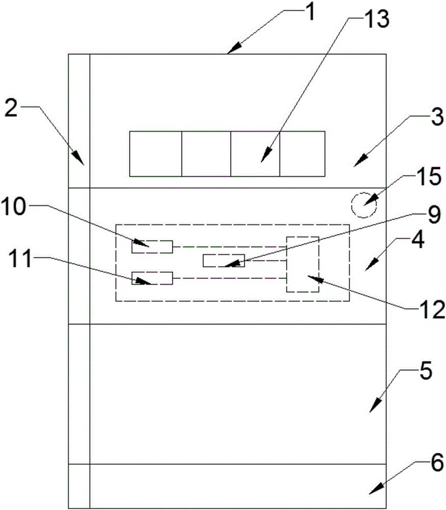
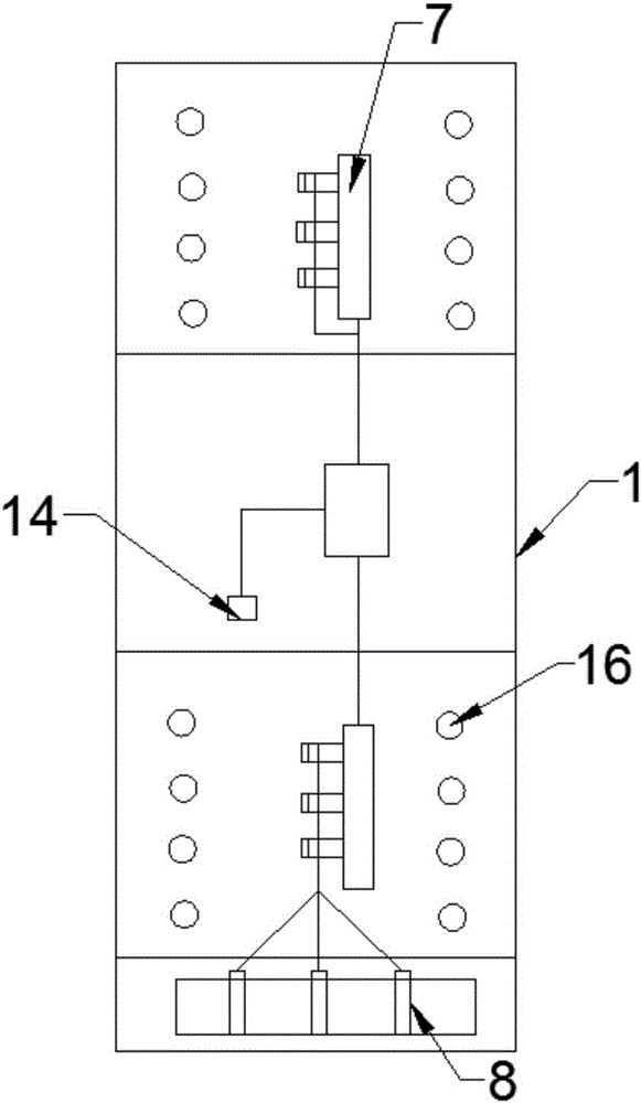
[0015] Such as figure 1 and figure 2 As shown, a novel multifunctional metering cabinet includes a cabinet body 1 and a cabinet door 2, the cabinet door 2 is hinged to one side of the cabinet body 1, and the cabinet body 1 is provided with an open metering chamber 3 from top to bottom, The control room 4, the closed metering room 5 and the busbar room 6, the open metering room 3 and the closed metering room 6 are provided with an integrated current transformer 7, the busbar room 6 is provided with a power supply line 8, and the integrated The current transformers 7 are all connected in series with the power supply line 8, and the control room 4 is provided with a wireless signal transmitter 9, a temperature sensor 10, a smoke sensor 11 and a mic...


PUM


Abstract

The invention discloses a novel multifunctional measuring cabinet, and relates to the field of electrical equipment. The novel multifunctional measuring cabinet comprises a cabinet body and a cabinet door, wherein the cabinet door is hinged with one side of the cabinet body; the cabinet body is internally provided with an open measuring chamber, a control chamber, a closed measuring chamber and a busbar chamber from top to bottom; the open measuring chamber and the closed measuring chamber are respectively and internally provided with an integrated current transformer; the busbar chamber is internally provided with an incoming power line; the integrated current transformers are connected with the incoming power line in series; the control chamber is internally provided with a wireless signal emission device, a temperature sensor, a smoke sensor and a microprocessor; the microprocessor is respectively connected with the wireless signal emission device, the temperature sensor and the smoke sensor; the integrated current transformers are respectively connected with the microprocessor by a lead. The novel multifunctional measuring cabinet realizes the function of measurement error correction by means of the two groups of current transformers, and can transmit measuring information and danger signals in time by using the wireless signal emission device, thus realizing intelligent management, and being worth popularizing.

Description

technical field [0001] The invention relates to the field of electrical equipment, in particular to a novel multifunctional metering cabinet. Background technique [0002] With the continuous advancement of the national smart grid construction, the quality of my country's electric energy metering instruments continues to improve, and the types and quantities continue to increase. Therefore, new requirements are put forward for the management of electric energy metering assets. Metering power distribution cabinets are indispensable in power equipment. Part of it is widely used in power equipment. The existing metering cabinets are relatively simple in design, and can only realize the installation of metering devices such as electric energy meters. With the development of technology and the progress of society, the requirements for electric energy measurement are getting higher and higher. After years of development, it is now possible to reliably realize the functions of remo...

Claims


Application Information

Patent Timeline
IPC IPC(8): H02B1/30H02B1/56H02B1/32
CPCH02B1/30H02B1/32H02B1/565
Inventor 黄文保刘亚冬俞磊
Owner 繁昌县易能科技有限责任公司
Learn More