A heat and power cogeneration unit controller

A cogeneration unit and controller technology, applied in the direction of parallel feeding arrangement of a single network, can solve the problems of large error of cogeneration unit and shock of cogeneration unit

Active Publication Date: 2019-08-09
ENN SCI & TECH DEV
View PDF3 Cites 0 Cited by
  • Summary
  • Abstract
  • Description
  • Claims
  • Application Information

AI Technical Summary

Problems solved by technology

[0006] The purpose of the present invention is to provide a cogeneration unit controller, which is used to solve the quasi-synchronous grid connection of the cogeneration unit due to the large err

Method used


Image

  • A heat and power cogeneration unit controller
  • A heat and power cogeneration unit controller
  • A heat and power cogeneration unit controller

Examples


Embodiment Construction

[0026] In order to further illustrate the controller of the combined heat and power unit provided by the embodiment of the present invention, a detailed description will be given below in conjunction with the accompanying drawings.

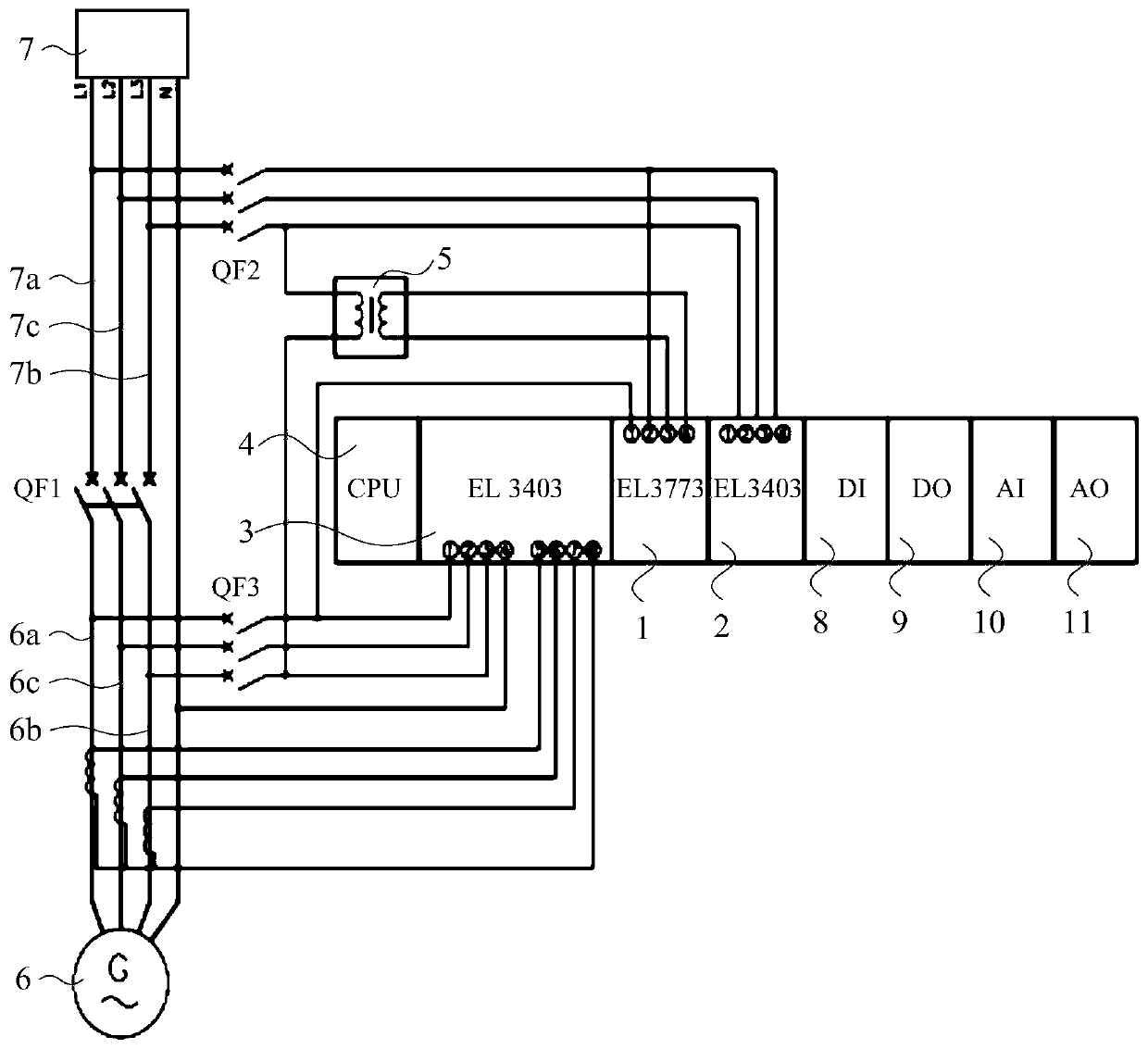
[0027] see figure 1 , the cogeneration unit controller provided by the embodiment of the present invention includes a first data acquisition unit 1 and a central processing unit 4, wherein the first data acquisition module 1 is connected to the cogeneration unit 6 and the grid 7 respectively, and the first data acquisition unit Unit 1 is used to collect the real voltage value of the first phase of the power grid at the integration point of the cogeneration unit 6 in the grid 7; the first data acquisition unit 1 is also used to collect the real voltage value of the cogeneration unit 6; the first data The acquisition unit 1 is also used to acquire the slip voltage between the second phase of the power grid at the merge point and the second phase of ...


PUM


Abstract

The invention discloses a controller for a heat and power cogeneration unit, relates to the technical field of heat and power cogeneration, and aims to reduce the impact on the heat and power cogeneration unit when the quasi-synchronous grid connection operation is performed on the heat and power cogeneration unit. The controller includes a first data acquisition unit and a central processing unit, and the first data acquisition unit is used to collect the actual value of the first phase voltage of the first phase of the power grid at the merge point, and collect the first phase voltage of the combined heat and power unit. The real value of the first phase voltage of the unit, the slip voltage between the second phase of the power grid at the acquisition point and the second phase of the cogeneration unit; the central processing unit is used to The real value of the voltage of the first phase of the unit, the coincidence degree of the voltage waveform of the first phase of the computer unit and the voltage waveform of the first phase of the grid. The heat and power cogeneration unit controller provided by the invention is used for controlling the heat and power cogeneration unit.

Description

technical field [0001] The invention relates to the technical field of heat and power cogeneration, in particular to a controller for a heat and power cogeneration unit. Background technique [0002] Combined Heat And Power (CHP) unit is a unit that simultaneously generates electricity and heat from the same fuel. It has the advantages of saving energy, improving fuel thermal efficiency, and reducing exhaust emissions, so it has attracted widespread attention. [0003] At present, the working status of the combined heat and power unit usually includes the isolated grid status in which the load is supplied independently, and the grid-connected status in which the load is supplied with power together with the grid. When the co-generation unit is required to work in the grid-connected status, it is usually Connecting the combined heat and power unit to the grid is to perform grid-connected operation on the combined heat and power unit. [0004] When cogeneration units are conn...

Claims


Application Information

Patent Timeline
IPC IPC(8): H02J3/44
CPCH02J3/44
Inventor 杨向阳李文乐
Owner ENN SCI & TECH DEV
Why Eureka
Try Eureka