Circuit arrangement and method for operating the circuit arrangement

A technology of circuit devices and leakage paths, applied in the field of circuit devices, can solve problems such as insulation resistance reduction, undesired release and control commands, etc., to achieve the effect of increasing resistance value, suppressing wrong release, and ensuring reliable operation

Active Publication Date: 2021-01-01
SIEMENS AG
View PDF7 Cites 0 Cited by
  • Summary
  • Abstract
  • Description
  • Claims
  • Application Information

AI Technical Summary

Problems solved by technology

If the control unit is used under harsh climatic ambient conditions (e.g. off-shore, coastal, heavily polluted air, extreme air humidity), leakage paths (Kriechwege) can form which reduce the insulation resistance
This can lead to potential propagation at the switching element as well as at the clamping position, which can lead to undesired release and control commands

Method used


Image

  • Circuit arrangement and method for operating the circuit arrangement
  • Circuit arrangement and method for operating the circuit arrangement
  • Circuit arrangement and method for operating the circuit arrangement

Examples


Embodiment Construction

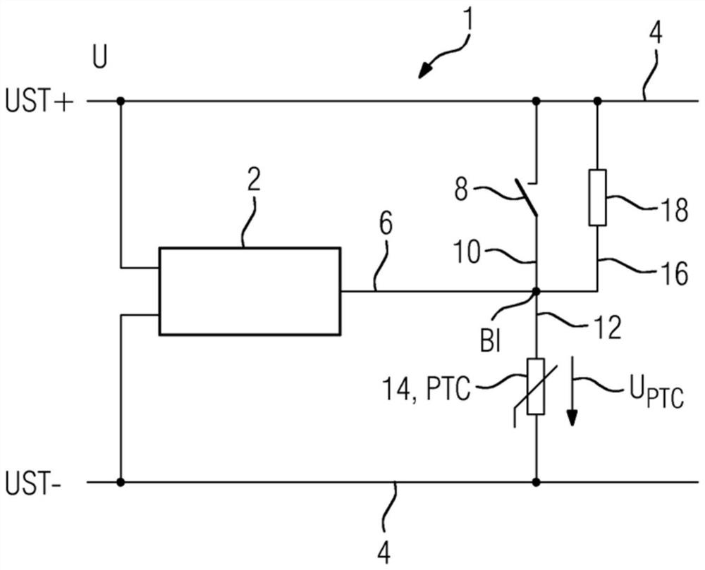
[0031] figure 1 The circuit arrangement 1 is shown schematically. The circuit arrangement 1 comprises a controller 2 , in particular a motor control unit, which is connected via electrical terminals and via electrical conductors designed as distribution lines 4 to the positive UST+ and secondly to the negative UST− of the associated voltage source. The negative pole UST- can also be the ground of the circuit. The controller 2 is thus supplied with an operating voltage U which corresponds to the potential difference between the positive pole UST+ and the negative pole UST−. The operating voltage U of the controller 2 is also referred to as the control voltage.

[0032] Here, the controller 2 is used in this exemplary embodiment to control a corresponding motor and has at least one output (not shown here) which is directly or indirectly connected to the motor. Also known as Motor Control Unit (MCU, Motor Control Unit) in English. Instead of a motor, the controller 2 can also...


PUM


Abstract

The invention relates to a circuit arrangement (1) having a controller (2) with a binary input (6) for detecting the switching state of a corresponding switch (8), wherein the input (6) ) is connected to a pull-down resistor (14), which achieves a low heat generation in all possible operating states while detecting possible switching states particularly reliably. For this purpose, according to the invention, the pull-down resistor (14) is a cold conductor.

Description

technical field [0001] The invention relates to a circuit arrangement having a controller with at least one binary input. It also relates to the corresponding operating method. Background technique [0002] In many cases, control devices or controllers with binary inputs are used for controlling the motors. An example of this is a so-called motor control unit (MCU). The release and feedback of the corresponding switching device or switch are queried via its binary input and a command for operating the motor is given. Typically, the type of input is "active high", which switches from a logic 0 (low) to 1 (high) from a certain switching threshold (usually eg 0.5*control voltage) under the condition of an applied potential. Release, feedback and commands are guided by various switching elements such as auxiliary switches, signaling switches and position switches, as well as by clamping positions. [0003] Since this is a binary input with a generally high input impedance (u...

Claims


Application Information

Patent Timeline
Patent Type & Authority Patents(China)
IPC IPC(8): G01R31/327G01R15/04G01R27/02
CPCG01R31/327G01R15/04G01R19/32
Inventor C.弗洛奥斯H.E.克吕佩尔
Owner SIEMENS AG
Why Eureka
Try Eureka