Photovoltaic detector read-out unit circuit applying inverted voltage follower

A voltage follower, photovoltaic detector technology, applied in instruments, adjusting electrical variables, control/regulating systems, etc., can solve the problems of increased input resistance, unguaranteed, and decreased injection efficiency of the readout unit circuit, so as to occupy the chip. Small area, background suppression, and constant injection efficiency

Inactive Publication Date: 2014-03-26
KUNMING INST OF PHYSICS
View PDF7 Cites 0 Cited by
  • Summary
  • Abstract
  • Description
  • Claims
  • Application Information

AI Technical Summary

Problems solved by technology

The transconductance of the transistor is related to its drain current. When the detector signal is small, that is, when the output current is small, the transconductance of the injection transistor decreases, and the input resistance of the readout unit circuit increases, resulting in a decrease in injection efficiency. Affect the performance of the detector
In the direct injection readout unit circuit, the bias voltage of the detector is related to the overdrive voltage of the injection transistor, and the overdrive voltage of the injection transistor is related to its threshold voltage and drain current, so that the bias voltage of the detector is in different Under different temperature conditions and different detector output currents, it will change, and the stability of the detector bias cannot be guaranteed, which will lead to the drift of the detector performance.
In short, the injection efficiency and detector bias of the direct injection readout unit circuit are related to the output photocurrent of the detector, which cannot guarantee a high injection efficiency and provide a constant and uniform zero bias voltage.

Method used


Image

  • Photovoltaic detector read-out unit circuit applying inverted voltage follower
  • Photovoltaic detector read-out unit circuit applying inverted voltage follower
  • Photovoltaic detector read-out unit circuit applying inverted voltage follower

Examples


Embodiment Construction

[0017] The present invention will be described in further detail through examples below in conjunction with the accompanying drawings, but the protection scope of the present invention is not limited to the following examples.

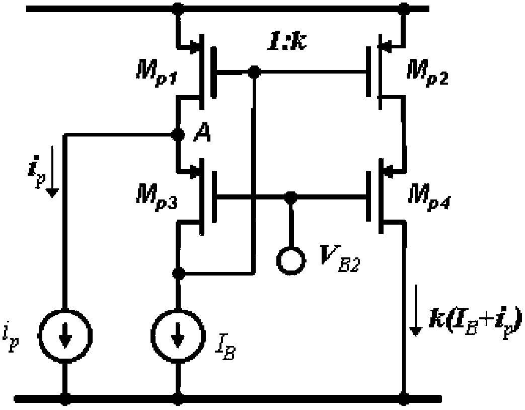
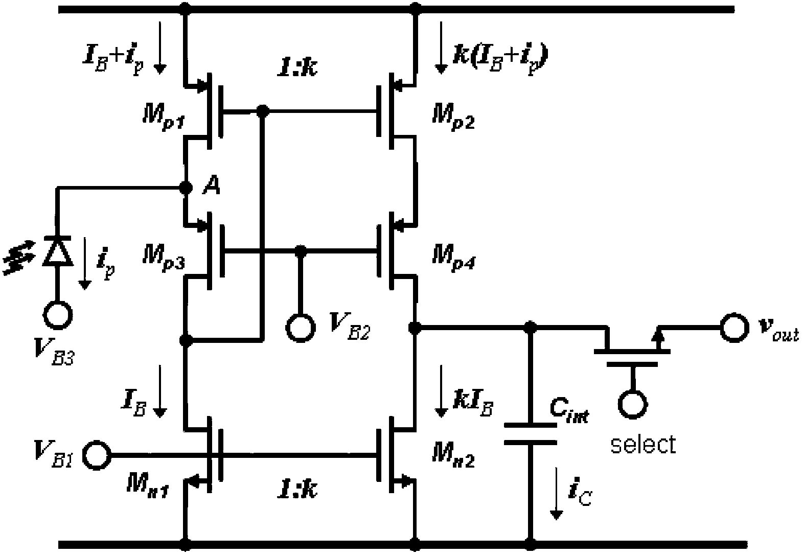
[0018] The main circuit of the present invention is a cascaded current mirror circuit composed of an inverted voltage follower, such as figure 1 shown. Transistor M p1 , M p3 with M p2 , M p4 To form a cascaded current mirror circuit, the transistor M p1 with transistor M p2 With the same gate-source voltage, it can be known from the working principle of the transistor that the transistor M p2 The drain current of the transistor M p1 There is an exact correspondence between the drain currents. exist figure 1 In the circuit, it is assumed that the transistor M p1 with transistor M p2 The parameters are the same, then the transistor M p2 The drain current of the transistor M p1 The drain current is the same, that is, the current gain of th...


PUM


Abstract

The invention relates to a photovoltaic detector read-out unit circuit applying an inverted voltage follower. The photovoltaic detector read-out unit circuit comprises a cascade current mirror circuit, a current integrating circuit and a bias voltage generating circuit, wherein transistors (Mp1 and Mp3) and transistors (Mp2 and Mp4) form the cascade current mirror circuit; transistors (Mp2, Mp4 and Mn2) and an integrating capacitor (Cint) form the current integrating circuit; and transistors (MBn1, MBn2, MBp1 and MBp2) form the bias voltage generating circuit. According to the circuit, an amplifier is not needed, the power loss is low, lower input resistance is realized and is unrelated to current of a detector, and the constant injection efficiency can be realized; bias voltage of the detector can be controlled accurately, and constant bias voltage of the detector can be provided; current gain of the read-out unit circuit can be changed through a dimension ratio of the transistors of a current mirror; a background current deduction circuit can be conveniently added, background suppression is realized, and the dynamic range of the circuit is enlarged; and the dynamic range is large, and input light current higher than bias current can be processed.

Description

technical field [0001] The invention relates to a readout unit circuit of a photovoltaic type infrared focal plane detector. Background technique [0002] In the infrared focal plane detector, the readout unit circuit is a circuit that interfaces with the detector, and its main function is to extract, amplify, integrate and convert the weak photocurrent generated by the detector into a voltage signal and then output it to the subsequent multiplex transmission circuit . As an interface between the detector and the multiplexer, the readout unit circuit is a key component, and its performance determines the performance of the entire readout circuit. [0003] One of the main functions of the readout unit circuit is to extract the detector photocurrent and inject it into the integration circuit, so one of its key parameters is the injection efficiency. The injection efficiency of the readout unit circuit is defined as the ratio of the current injected into the readout unit circ...

Claims


Application Information

Patent Timeline
Patent Type & Authority Patents(China)
IPC IPC(8): G05F3/26
Inventor 姚立斌刘传明胡志斌洪闻青王晓东吴晓飚苏俊波李云川赵海生苏兰朱江
Owner KUNMING INST OF PHYSICS
Why Eureka
Try Eureka