Self-unloading double-body barn
A two-body, granary technology, applied in fruit hanging devices, botany equipment and methods, gardening, etc., can solve the problems of single function, large land occupation, high cost, etc., and achieve the effect of compact and simplified structure, reasonable structure and low cost
- Summary
- Abstract
- Description
- Claims
- Application Information
AI Technical Summary
Problems solved by technology
Method used
Image
Examples
Embodiment 1)
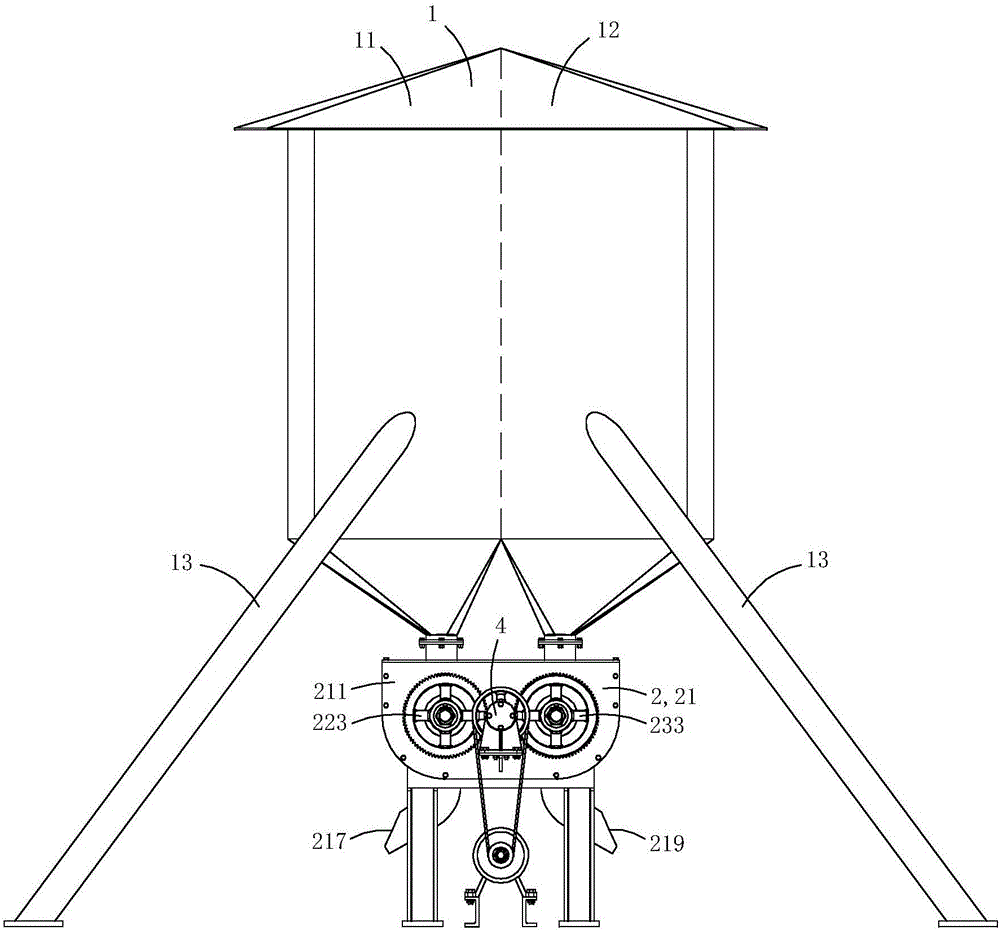
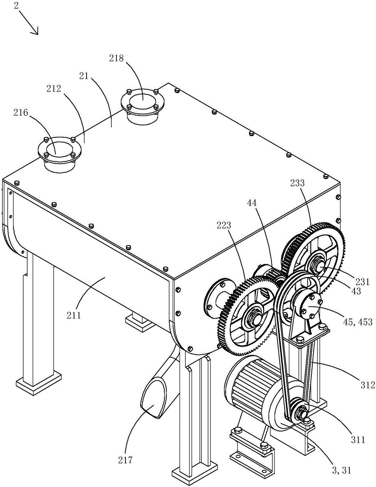
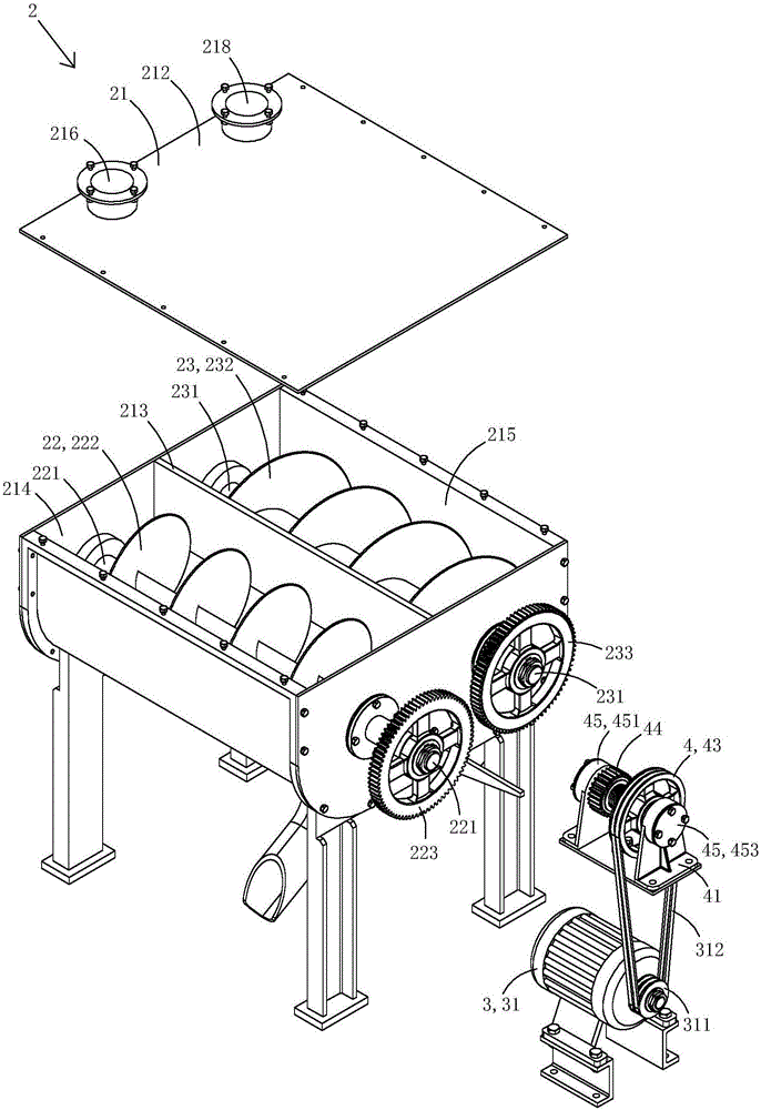
[0037] Figure 1 to Figure 8 A first embodiment of the invention is shown.
[0038] Present embodiment is a kind of self-unloading two-body granary, see Figure 1 to Figure 8 Shown, comprise double-body warehouse 1 and be arranged on the grain unloading device 2 below double-body warehouse.
[0039] The double-body warehouse 1 has a first warehouse 11 and a second warehouse 12 arranged side by side. The bottom of the first warehouse is conical, and the center of the bottom has a first outlet; the bottom of the second warehouse is also conical, and the bottom of the second warehouse is conical. There is a second outlet in the center. In this embodiment, four supporting pillars 13 are arranged at the lower part of the double-body warehouse, and the double-body warehouse stands on the ground through the four supporting pillars. In practice, it is also possible not to support the pillars, but directly fix the double-body warehouse on the wall or on the carrier, such as using th...
Embodiment 2)
[0059] Figure 9 to Figure 1 2 shows a second embodiment of the present invention.
[0060] This embodiment is basically the same as Embodiment 1, the difference is: see Figure 9 to Figure 1 As shown in 2, the side end of the limit block in the present embodiment is closer to the pulley, the side end of the pulley closer to the limit block, and both sides of the clutch transmission gear are provided with gear teeth 5 , each tooth is provided with a bearing surface 51 and a guide surface 52, and each guide surface is an arc surface. When the clutch transmission gear translates towards the direction of the limit stop, the thrust surface of the gear teeth of the clutch transmission gear finally abuts against the thrust surface of the gear teeth of the limit stop; when the clutch transmission gear translates towards the direction of the pulley, the clutch The thrust bearing surface of the gear teeth of the transmission gear finally abuts against the thrust bearing surface of th...
Embodiment 3)
[0062] Figure 13 to Figure 20 A third embodiment of the invention is shown.
[0063] This embodiment is basically the same as Embodiment 2, the difference is: see Figure 13 to Figure 20 As shown, at least one information collector 6 is installed in the first warehouse and the second warehouse.
[0064] The information collecting instrument 6 includes a cylindrical shell 61, a main gear 62 which is rotatably arranged in the cylindrical shell, four traveling roller tubes 63 which are rotatably arranged on the cylindrical casing, and pinion gears 64 which are fixedly arranged on the outer walls of each traveling roller tube. The prime mover 65 that drives the main gear to rotate; the four auxiliary gears are evenly arranged on the outer peripheral side of the main gear, and are symmetrically arranged in the center; when the main gear rotates, it drives the auxiliary gears to rotate synchronously.
[0065] In this embodiment, the outer peripheral wall of the main gear is provi...
PUM
 Abstract
Description
Claims
Application Information
 - R&D
- Intellectual Property
- Life Sciences
- Materials
- Tech Scout
- Unparalleled Data Quality
- Higher Quality Content
- 60% Fewer Hallucinations
Browse by: Latest US Patents, China's latest patents, Technical Efficacy Thesaurus, Application Domain, Technology Topic, Popular Technical Reports.
© 2025 PatSnap. All rights reserved.Legal|Privacy policy|Modern Slavery Act Transparency Statement|Sitemap|About US| Contact US: help@patsnap.com


