
Automatic irrigation device in garden

An automatic irrigation and gardening technology, applied in watering devices, horticulture, botanical equipment and methods, etc., can solve the problems of affecting irrigation efficiency, consumption of large water sources, inconvenient operation, etc., and achieve a solid structure, avoid waste, and facilitate maintenance. Effect

Inactive Publication Date: 2017-05-31
彭伟成
View PDF5 Cites 0 Cited by
  • Summary
  • Abstract
  • Description
  • Claims
  • Application Information

AI Technical Summary

Problems solved by technology

[0002] At present, with the development of modernization, landscaping in urban construction has received great attention, but my country is a country with relatively scarce water resources, and the water used for landscaping is also urgently needed to achieve the effect of environmental protection and water saving, and garden irrigation needs to consume a lot Generally, garden irrigation uses nearby river water, but some green places such as lawns and flower beds are far away from the river, so they need to be transported by vehicles and irrigated with the help of irrigation devices. The structure of general irrigation devices is complex. , the operation is inconvenient, which affects the irrigation efficiency, and some improvements need to be made in order to better improve the irrigation efficiency

Method used


Image

  • Automatic irrigation device in garden
  • Automatic irrigation device in garden
  • Automatic irrigation device in garden

Examples


Embodiment 1

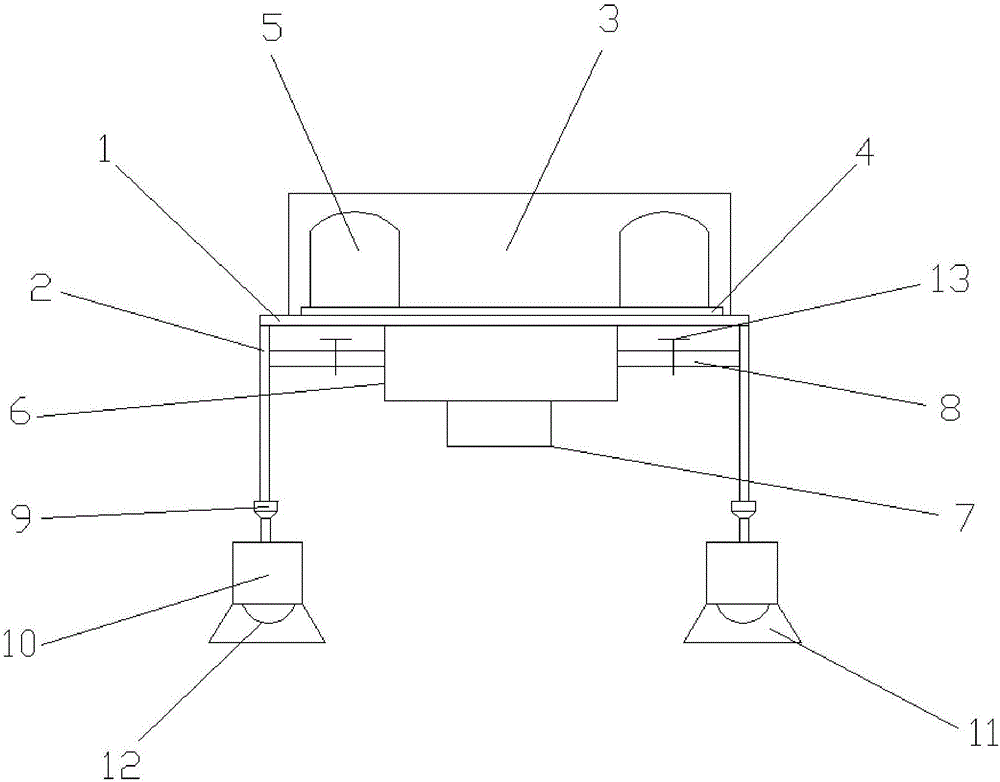
[0026] refer to figure 1 As shown, a garden automatic irrigation device includes a load-bearing platform 1, a first water pipe 2 is arranged below the load-bearing platform 1, a water storage device 3 is arranged above the load-bearing platform 1, and the water storage device 3 A mounting seat 4 is provided inside, and a pressure device 5 is installed on the mounting seat 4, and the pressure device 5 is fixedly connected with the mounting seat 4. A water pump 6 is provided under the load-bearing platform 1, and the water pump 6 is connected to the load-bearing platform. The board 1 is fixedly connected, the water pump 6 communicates with the water storage device 3, a controller 7 is arranged under the water pump 6, a second water pipe 8 is connected to the water pump 6, and a regulating valve is arranged on the first water pipe 2 9 and a water buffering device 10, the water buffering device 10 is located at the lower end of the first water pipe 2, the regulating valve 9 is loc...

Embodiment 2

[0045] refer to figure 1 As shown, a garden automatic irrigation device includes a load-bearing platform 1, a first water pipe 2 is arranged below the load-bearing platform 1, a water storage device 3 is arranged above the load-bearing platform 1, and the water storage device 3 A mounting seat 4 is provided inside, and a pressure device 5 is installed on the mounting seat 4, and the pressure device 5 is fixedly connected with the mounting seat 4. A water pump 6 is provided under the load-bearing platform 1, and the water pump 6 is connected to the load-bearing platform. The board 1 is fixedly connected, the water pump 6 communicates with the water storage device 3, a controller 7 is arranged under the water pump 6, a second water pipe 8 is connected to the water pump 6, and a regulating valve is arranged on the first water pipe 2 9 and a water buffering device 10, the water buffering device 10 is located at the lower end of the first water pipe 2, the regulating valve 9 is loc...

Embodiment 3

[0064] refer to figure 1 As shown, a garden automatic irrigation device includes a load-bearing platform 1, a first water pipe 2 is arranged below the load-bearing platform 1, a water storage device 3 is arranged above the load-bearing platform 1, and the water storage device 3 A mounting seat 4 is provided inside, and a pressure device 5 is installed on the mounting seat 4, and the pressure device 5 is fixedly connected with the mounting seat 4. A water pump 6 is provided under the load-bearing platform 1, and the water pump 6 is connected to the load-bearing platform. The board 1 is fixedly connected, the water pump 6 communicates with the water storage device 3, a controller 7 is arranged under the water pump 6, a second water pipe 8 is connected to the water pump 6, and a regulating valve is arranged on the first water pipe 2 9 and a water buffering device 10, the water buffering device 10 is located at the lower end of the first water pipe 2, the regulating valve 9 is loc...


PUM


Abstract

The invention discloses an automatic irrigation device in a garden. The automatic irrigation device comprises a load-bearing bedplate, wherein a first water pipe is arranged below the load-bearing bedplate; a water storage device is arranged above the load-bearing bedplate; a mounting base is arranged in the water storage device; a pressure device is arranged on the mounting base and is fixedly connected with the mounting base; a water pump is arranged below the load-bearing bedplate, is fixedly connected with the load-bearing bedplate, and communicates with the water storage device; a controller is arranged below the water pump; the water pump is connected with a second water pipe; an adjusting valve and a water retarding device are arranged on the first water pipe; the water retarding device is positioned at the lower end of the first water pipe; the adjusting valve is positioned above the water retarding device; the lower end of the water retarding device is provided with a watering cover and a spray nozzle; and the watering cover is arranged at the outer side of the spray nozzle by covering. The automatic irrigation device in the garden can appropriately perform irrigation to avoid waste of water resources, and is convenient to maintain; and meanwhile, the automatic irrigation device has the advantage of good adjustability.

Description

technical field [0001] The invention specifically relates to a garden automatic irrigation device. Background technique [0002] At present, with the development of modernization, landscaping in urban construction has received great attention, but my country is a country with relatively scarce water resources, and the water used for landscaping is also urgently needed to achieve the effect of environmental protection and water saving, and garden irrigation needs to consume a lot Generally, garden irrigation uses nearby river water, but some green places such as lawns and flower beds are far away from the river, so they need to be transported by vehicles and irrigated with the help of irrigation devices. The structure of general irrigation devices is complex. , the operation is inconvenient, which affects the irrigation efficiency, and some improvements need to be made in order to better improve the irrigation efficiency. Contents of the invention [0003] The technical prob...

Claims


Application Information

Patent Timeline
Patent Type & Authority Applications(China)
IPC IPC(8): A01G25/02A01G25/16C22C30/06
CPCA01G25/02A01G25/165C22C30/02C22C30/06
Inventor 彭伟成
Owner 彭伟成
Learn More