Using method of dehumidifying structure for operating room of hydropower station

A technology for operating rooms and hydropower stations, applied in separation methods, chemical instruments and methods, gas treatment, etc., can solve problems affecting the normal operation of electrical equipment in hydropower stations, erosion and oxidation of heat exchangers by humid air, damage to heat exchangers, etc., to achieve Continuously stabilize dehumidification performance, maintain dehumidification performance, and ensure favorable support effect

Inactive Publication Date: 2017-05-31
重庆靠岸机电设备有限公司
View PDF0 Cites 1 Cited by
  • Summary
  • Abstract
  • Description
  • Claims
  • Application Information

AI Technical Summary

Problems solved by technology

In the traditional dehumidifier, due to the high content of water vapor in the working environment, the heat exchanger is easily eroded and oxidized by the humid air when exchanging heat with the air, which in turn causes damage to the heat exchanger and affects the normal operation of the electrical equipment of the hydropower station. Work

Method used


Image

  • Using method of dehumidifying structure for operating room of hydropower station
  • Using method of dehumidifying structure for operating room of hydropower station
  • Using method of dehumidifying structure for operating room of hydropower station

Examples


Embodiment 1

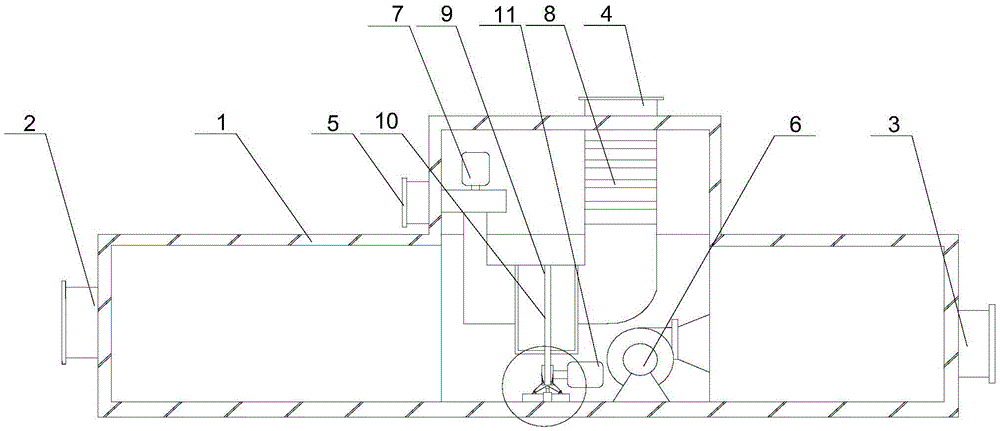
[0028] Such as Figure 1 to Figure 4 Shown, the present invention comprises the following steps:

[0029] A The cold air in the operating room enters the dehumidification wheel through the air inlet;

[0030] The humid air in the B operating room is processed in the treatment area, the dehumidification wheel is driven to rotate slowly, and the saturated water vapor in the treatment area enters the regeneration area;

[0031] C When the motor belt is loose, the tension of the belt can be restored under the adjustment of the tension adjustment mechanism;

[0032] D Inject fresh air through the regenerative air inlet, and the heater will heat the fresh air;

[0033] E Finally, the dry air is discharged from the casing and reflows into the operating room;

[0034] The above steps include a casing 1, on which the casing 1 is provided with an air inlet 2, an air outlet 3, a regenerative air inlet 4 and a regenerative air outlet 5, and a fan 6 and a heater 8 are installed in the c...

Embodiment 2

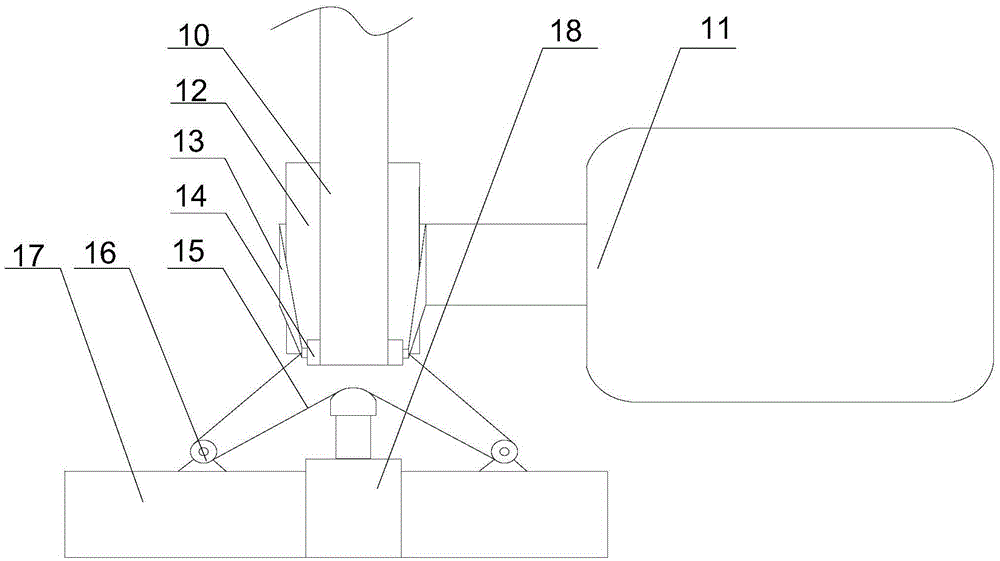
[0037] Such as figure 2 and Figure 4 As shown, in this embodiment, on the basis of Embodiment 1, the roller 14 arranged tangentially to the pulley 12, the pulley 12, the roller 14 and the dehumidification runner 9 are connected by the belt 10, and the roller 14 and the belt 10 A pressure sensor 19 is installed at the tangent, and the pulley 12 is connected with the roller 14 by a connecting rod 13. A support 17 is arranged in the casing. A cylinder 18 and a plurality of fixed pulleys 16 are installed on the support 17. The pressure sensor 19 is connected with the The driving device of the cylinder 18 is connected, and a plurality of fixed pulleys 16 are symmetrically arranged on both sides of the output end of the cylinder 18. The two ends of the rotating shaft of the roller 14 are connected with a traction line 15, and the traction line 15 bypasses the two fixed pulleys 16 and the cylinder 18 The output end forms a pulley block. The motor 11 drives the dehumidification ru...

Embodiment 3

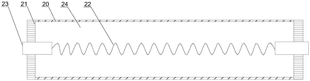
[0039] Such as Figure 4 As shown, this embodiment is based on Embodiment 1, the connecting rod 13 is an elastic plastic rod, and the two ends of the elastic plastic rod are sleeved on the rotating shafts of the pulley 12 and the roller 14 respectively. In order to prevent the roller 14 from moving with the belt 10 when rotating, the connecting rod 13 connects the pulley 12 to the roller 14. When the roller 14 is pulled at the output end of the cylinder 18, the connecting rod 13 made of elastic plastic will produce a small deformation to The movement of the rollers 14 is accommodated while ensuring favorable support of the rollers 14 .


PUM


Abstract

The invention discloses a using method of a dehumidifying structure for an operating room of a hydropower station. The using method comprises the following steps: enabling cold air to enter a dehumidifying rotating wheel through an air inlet; treating wet air in the operating room in a treating zone; driving the dehumidifying rotating wheel to rotate slowly, and enabling water vapor tending to be saturated in the treating zone to enter a regenerating zone; keeping normal rotation of a motor belt under the adjustment of a tension adjusting mechanism; injecting fresh air through a regenerating air inlet, and heating the fresh air by a heater; finally exhausting dry air out of a shell, and enabling the dry air to reflow into the operating room.

Description

technical field [0001] The invention relates to a dehumidifier, in particular to a method for using a dehumidification structure used in an operation room of a hydropower station. Background technique [0002] A hydropower station is a comprehensive engineering facility that converts water energy into electrical energy, also known as a hydropower plant. It includes a series of hydropower station buildings and various hydropower station equipment built for the use of water energy to produce electricity. Use these buildings to concentrate the drop of natural water flow to form a water head, collect and adjust the flow of natural water flow, and send it to the water turbine. Through the joint operation of the water turbine and the generator, the concentrated water energy is converted into electrical energy, and then through the transformer, switch Stations and transmission lines, etc. input electric energy into the grid. In conventional hydropower stations and tidal power sta...

Claims


Application Information

Patent Timeline
Patent Type & Authority Applications(China)
IPC IPC(8): B01D53/26B01D53/06
CPCB01D53/261B01D2257/80B01D2259/4009B01D2259/4508
Inventor 陈启友
Owner 重庆靠岸机电设备有限公司
Why Eureka
Try Eureka