
Test tube shaking device

A test tube and vertical plate technology, applied in the directions of transportation and packaging, mixer, dissolution, etc., can solve the problems of increasing the pain of patients and blood test personnel, increasing the workload of medical staff, and troublesome medical staff, so as to achieve diversity. , to achieve detachability, to ensure the effect of fluency

Active Publication Date: 2017-05-31
AFFILIATED HOSPITAL OF GUILIN MEDICAL UNIV
View PDF4 Cites 6 Cited by
  • Summary
  • Abstract
  • Description
  • Claims
  • Application Information

AI Technical Summary

Problems solved by technology

This causes the blood placed in the test tube to coagulate or even deteriorate after a long time; when it is used again, it must be collected again, which not only increases the workload of the medical staff, but also brings unnecessary troubles to the medical staff; It also increases the pain of the patient and the blood tester
Especially for children, it is more troublesome during the blood test
With the continuous advancement of science and technology, there are more and more scientific experiments, and the observation of experimental phenomena with test tubes is becoming more and more frequent. Shaking test tubes is a very important link in chemical experiments. At present, the work of shaking test tubes depends on It is done manually, and manual test tube shaking has the problems of uneven shaking and low efficiency, so an efficient test tube shaking device is urgently needed
[0003] However, the test tube shaking devices currently on the market can only shake the test tubes horizontally, and cannot shake the test tubes vertically, which affects the diversity of experiments.

Method used


Image

  • Test tube shaking device
  • Test tube shaking device
  • Test tube shaking device

Examples


Embodiment Construction

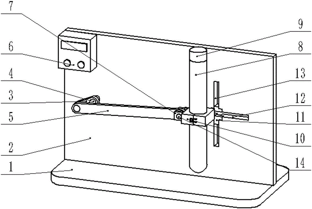
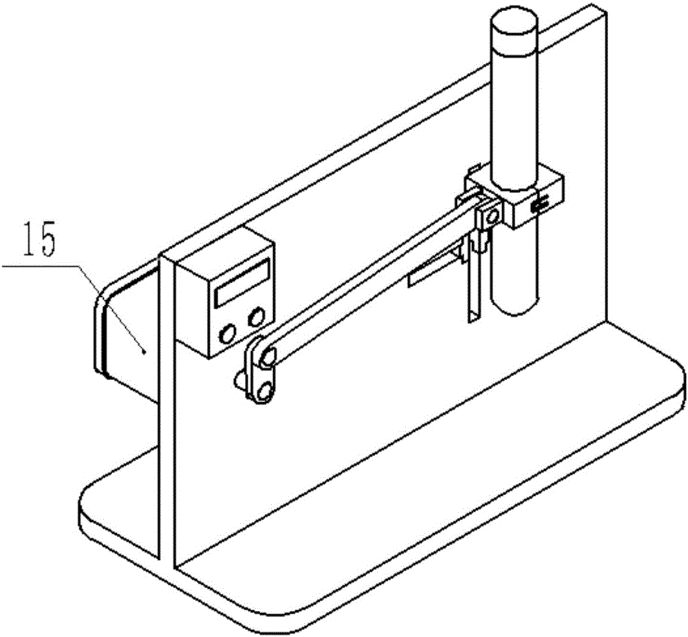
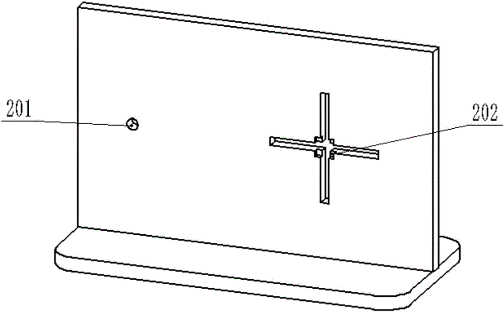
[0019] A test tube shaking device is composed of base 1, vertical plate 2, output shaft fixing hole 201, fixed magnet 202, crank 3, motor output shaft 4, connecting rod 5, control box 6, connecting block 7, test tube 8, test tube The plug 9, the test tube clamp 10, the reversing plate 11, the horizontal rail 12, the longitudinal rail 13, the connecting bolt 14 and the motor 15, the upper middle part of the base 1 is fixedly connected with the vertical plate 2, and the vertical plate 2 is provided with There is an output shaft fixing hole 201, the output shaft fixing hole 201 is sleeved with the motor output shaft 4 of the motor 15, the end of the motor output shaft 4 is fixedly connected to one end of the crank 3, and the other end of the crank 3 is connected to the connecting rod One end of the connecting rod 5 is fixedly connected, and the other end of the connecting rod 5 is connected to the connecting block 7 on the test tube clamp 10 by a connecting bolt 14. The test tube c...


PUM


Abstract

The invention discloses a test tube shaking device, and belongs to the field of experimental equipment. A middle part of the upper end of a base is fixedly connected with a vertical plate; an output shaft fixing hole is arranged in the vertical plate; a motor output shaft of the motor is sleeved with the output shaft fixing hole; the tail end of the motor output shaft is fixedly connected with one end of a crank; the other end of the crank is fixedly connected with one end of a connecting rod, the other end of the connecting rod is connected with a connection block on a test tube clamp through a connecting bolt; a test tube is clamped in the middle of the test tube clamp; an open end of the test tube is blocked by a test tube plug; a transverse track and a longitudinal track are arranged in the vertical plate; fixed magnets are arranged at four corners of the junction of the transverse track and the longitudinal track; a reversing plate is arranged on each fixed magnet; a control box is arranged on the vertical plate. The transverse shaking or longitudinal shaking function of the test tube is achieved through the transverse track, the longitudinal track and a sliding column and the diversity of experiments is achieved.

Description

Technical field [0001] The invention relates to a test tube shaking device, in particular to a device that realizes the horizontal or vertical shaking of a test tube through horizontal and vertical rails and sliding columns, and belongs to the field of experimental equipment. Background technique [0002] Every year when people do physical examinations, they do blood tests; that is, the human blood is drawn out and placed in a glass test tube, and then the test tube is placed on the blood sampling rack. Since the current blood collection specimen storage racks are fixed, they will not shake. This will cause the blood placed in the test tube to clot and even deteriorate after a long time; when it is used again, it must be collected again, which not only increases the workload of the medical staff, but also brings unnecessary trouble to the medical staff; It also increases the pain of the patient and the person under blood test. Especially for children during the blood test, it i...

Claims


Application Information

Patent Timeline
IPC IPC(8): B01F11/00
CPCB01F31/201B01F31/24B01F31/275
Inventor 孟祥震王报龙吴倩倩
Owner AFFILIATED HOSPITAL OF GUILIN MEDICAL UNIV
Learn More