
automatic drilling machine

A drilling machine and automatic technology, which is applied in the field of mechanical parts processing, can solve the problems of high labor cost, low processing efficiency of finished products, and low precision, and achieve the effect of saving labor cost and high processing efficiency

Active Publication Date: 2019-06-07
台山市富悦五金塑料制品有限公司
View PDF5 Cites 0 Cited by
  • Summary
  • Abstract
  • Description
  • Claims
  • Application Information

AI Technical Summary

Problems solved by technology

This manual stamping method requires high mold costs in the early stage, and in the stamping process, the finished product processing efficiency is low, the labor cost is high, and it is prone to low precision, many beryllium fronts, and indentations and cracks on the surface of the pipe fittings. Scratches and other issues

Method used


Image

  • automatic drilling machine
  • automatic drilling machine
  • automatic drilling machine

Examples


Embodiment Construction

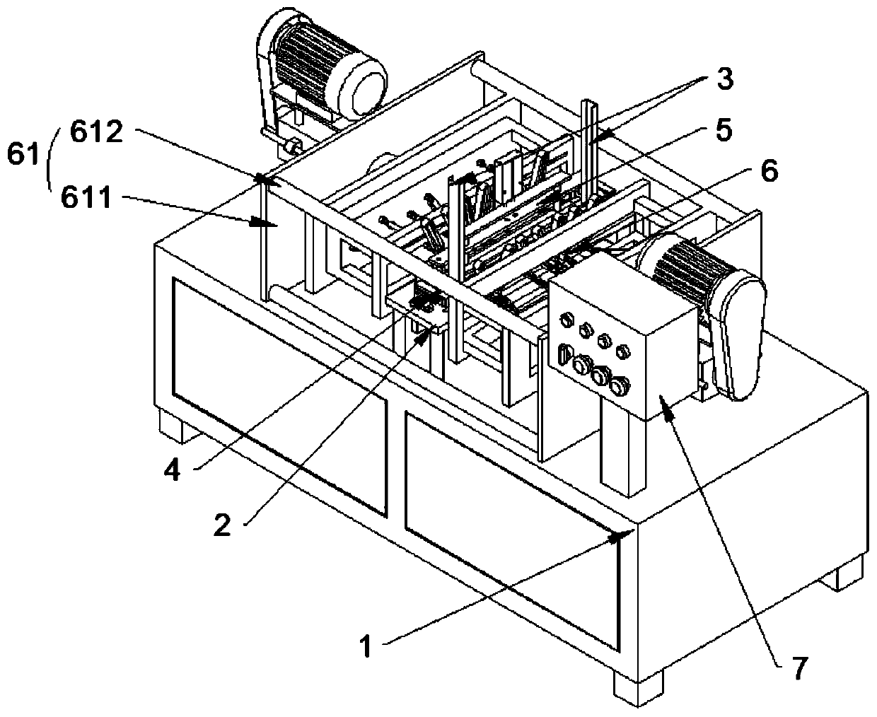
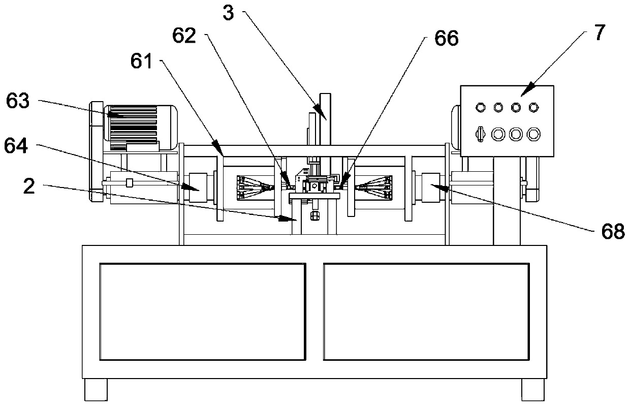
[0025] Please also see Figure 2 to Figure 4 , figure 2 It is a side view of an embodiment of an automatic drilling machine of the present invention; image 3 It is the front view of the automatic drilling machine embodiment of the present invention; Figure 4 It is a top view of an embodiment of the automatic drilling machine of the present invention. The automatic drilling machine includes a working platform 1 , a support frame 2 , a slide rail 3 , a pushing device 4 , a positioning device 5 , a drilling device 6 and a controller 7 .

[0026] The support frame 2 is erected on the working platform 1 , and the slide rail 3 is vertically erected on the support frame 2 . The pushing device 4 is fixed on the support frame 2 and is located on one side of the bottom of the slide rail 3 . The positioning device 5 is arranged on the other side of the bottom of the slide rail 3 . The drilling device 6 is fixed on the working platform 1 and used for drilling the workpiece positio...


PUM


Abstract

The invention relates to an automatic drilling machine. The automatic drilling machine comprises a working platform, a supporting frame, a sliding rail, a pushing device, a positioning device and a drilling device, wherein the supporting frame is erected on the working platform; the sliding rail is vertically erected on the supporting frame; the pushing device is fixed to the supporting frame and located on one side of the bottom of the sliding rail; the positioning device is arranged on the other side of the bottom of the sliding rail; and the drilling device is fixed to the working platform and used for conducting drilling on a to-be-machined workpiece positioned on the positioning device. Compared with the prior art, the drilling device can drill holes in the two sides of the to-be-machined workpiece at the same time, the size of the drilled holes meet the requirements, burrs and bruises are avoided, the machining efficiency is high, convenience and rapidness are achieved, and the labor cost is greatly lowered.

Description

technical field [0001] The invention relates to the field of mechanical parts processing, in particular to an automatic drilling machine. Background technique [0002] In the field of mechanical parts processing, it is usually necessary to drill holes in the workpiece. see figure 1 , which is a schematic diagram of the support tube structure. For example, when making the support pipe 1a of a barbecue oven, it is usually necessary to open a drill hole 2a on the support pipe 1a, and realize the connection between the support pipe 1a and other pipe fittings through the drill hole 2a. [0003] In the prior art, punching dies are usually used manually to realize the orifice. This manual stamping method requires high mold costs in the early stage, and in the stamping process, the finished product processing efficiency is low, the labor cost is high, and it is prone to low precision, many beryllium fronts, and indentations and cracks on the surface of the pipe fittings. scratch...

Claims


Application Information

Patent Timeline
Patent Type & Authority Patents(China)
IPC IPC(8): B23B39/22
CPCB23B39/22
Inventor 雷勉仪
Owner 台山市富悦五金塑料制品有限公司
Learn More