
Steel structure punching device

A drilling device and steel structure technology, applied in the direction of boring/drilling, drilling/drilling equipment, boring machine/drilling machine parts, etc., can solve the problems of poor product quality, low production efficiency, etc., and achieve the goal of reducing electric shock Hazards, reduced occupancy, increased flexibility of use

Active Publication Date: 2017-05-31
衡水久固钢结构有限公司
View PDF11 Cites 4 Cited by
  • Summary
  • Abstract
  • Description
  • Claims
  • Application Information

AI Technical Summary

Problems solved by technology

In order to improve the assembly efficiency of the steel structure and speed up the construction efficiency, the steel structure skeleton in the prior art is usually punched, bent and surface treated in the factory; it is directly transported to the construction site for assembly, which requires processing and processing of the steel structure. The processing puts forward higher requirements; the punching equipment in the prior art is usually not optimized for strip components such as steel structure components, and production failures caused by mismatches between equipment and product models and sizes often occur during actual processing. Low efficiency, poor product quality and many other problems

Method used


Image

  • Steel structure punching device
  • Steel structure punching device
  • Steel structure punching device

Examples


Embodiment 1

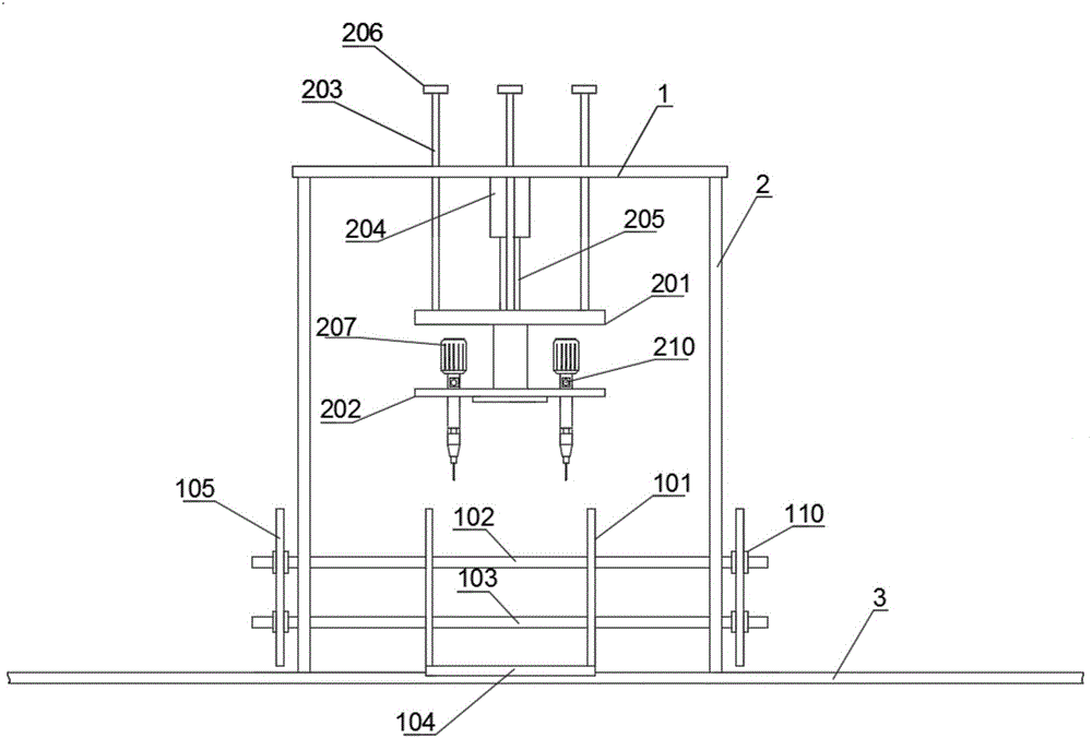
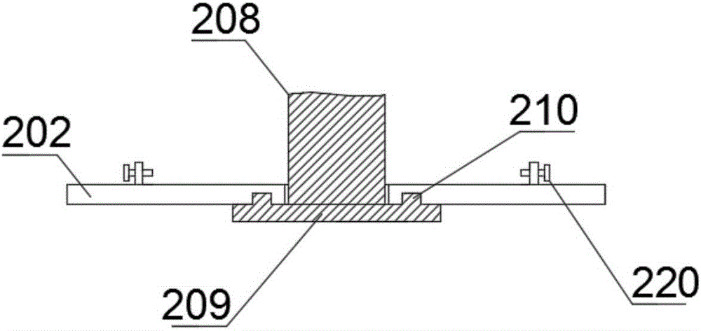
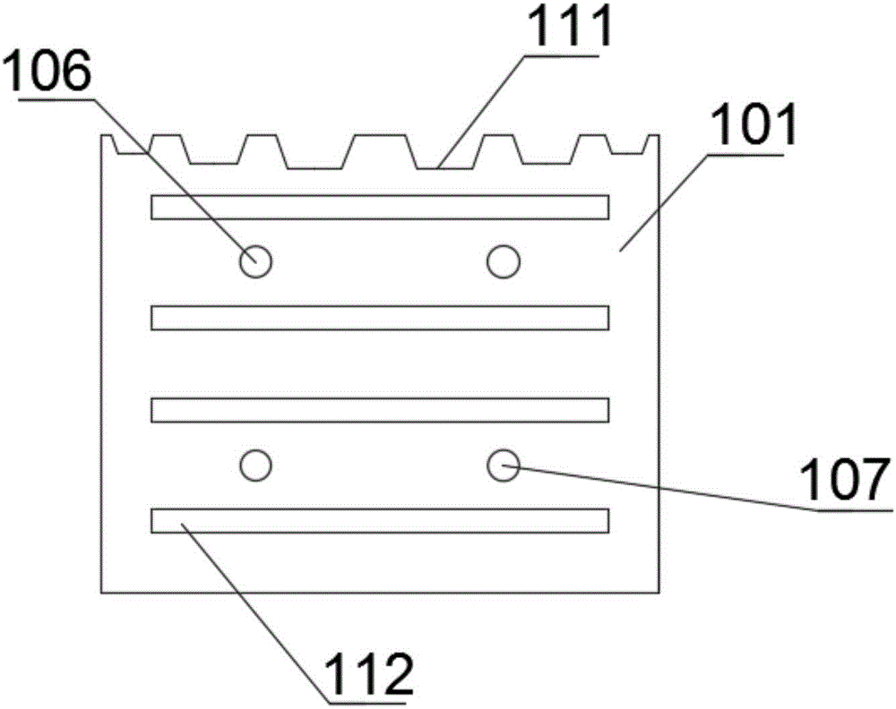
[0016] Such as Figure 1-5 As shown, the present embodiment provides a steel structure punching device, including a punching device, a working platform, a top plate 1, a column 2 and a slide rail 3; the top plate 1 is fixed on the ground through the column 2; the punching The device includes a mounting plate 201, a rotating plate 202, a sliding rod 203, a lifting column 204 and four punchers 207; the lifting column 204 is fixed on the bottom of the top plate 1, and its piston rod 205 is connected to the mounting plate 201; the sliding rod The upper part of 203 is movably installed on the top plate 1 through the slide hole arranged on the top plate 1, and the bottom of the slide bar 203 is fixedly connected with the mounting plate 201, and the top of the slide bar 203 is provided with a limit block 206; the bottom of the mounting plate 201 A connecting column 208 is provided, and a horizontal plate 209 is provided at the bottom of the connecting column 208; an annular slide rai...

Embodiment 2

[0018] Such as Figure 1-5 As shown, the present embodiment provides a steel structure punching device, which is different from Embodiment 1 in that a plurality of strip-shaped holes 112 are provided on the side walls of the vertical fixed plate 103 and the movable plate 105; A positioning bolt 220 for fixing the position of the cylindrical shell is provided at the mounting hole of the rotating disk 202; the positioning bolt 220 is installed on the rotating disk 202 through a vertical plate.


PUM


Abstract

The invention provides a steel structure punching device which comprises a punching device body, a working platform, a top plate, upright columns and a sliding rail. The punching device body is movably fixed on the top plate through a mounting disk; punchers of the punching device body are movably mounted on a rotating disk; and the rotating disk rotates relative to the mounting disk. The working platform comprises fixed plates and movable plates, and the fixed plates and the movable plates are movably connected through upper sliding rods and lower sliding rods. The steel structure punching device has the advantages of good universality, less occupied space and the like.

Description

technical field [0001] The invention relates to the technical field of steel structure processing, in particular to a steel structure drilling device. Background technique [0002] The steel structure is a kind of basic component made of section steel or steel plate, according to the requirements of use, through welding or bolt connection, etc., according to a certain law to form a load-bearing mechanism. Steel structures are widely used in various engineering constructions, such as steel bridges, steel workshops, steel gates, various large pipeline containers, high-rise buildings and tower rail mechanisms, etc. Due to the comprehensive advantages of light weight, easy installation, short construction period, good seismic performance, fast investment recovery and less environmental pollution, the steel structure system has been widely used in the construction industry. In order to improve the assembly efficiency of the steel structure and speed up the construction efficienc...

Claims


Application Information

Patent Timeline
Patent Type & Authority Applications(China)
IPC IPC(8): B23B41/00B23B39/16B23B47/00
CPCB23B39/161B23B41/00B23B47/00
Inventor 张振海
Owner 衡水久固钢结构有限公司
Learn More