
Process method of angle steel profiling cutter

A process method and cutting method technology, applied in the direction of manufacturing tools, metal processing equipment, metal processing machinery parts, etc., can solve problems such as increased difficulty, low efficiency, and poor cutting quality, so as to reduce the error rate of blanking and reduce the difficulty of operation , the effect of improving labor efficiency

Active Publication Date: 2017-05-31
CHINA 19TH METALLURGICAL FANGCHENGGANG DEVICE STRUCTURES
View PDF13 Cites 0 Cited by
  • Summary
  • Abstract
  • Description
  • Claims
  • Application Information

AI Technical Summary

Problems solved by technology

[0004] Usually, when drawing lines, due to the problem of personnel operation level and the difficulty of drawing lines on multiple sides, etc., the drawing lines are inaccurate; when cutting or sawing at the same time, there are easy errors between the reference line and the cutting line, resulting in material accumulation error
If the profile is processed and manufactured, the end faces are not on the same plane, that is, there are angles between several surfaces of the profile, the difficulty of the entire manufacturing process will be greatly increased: when drawing a line, one side needs to be drawn first, and then the angle is converted into a linear relationship, and then the other side is drawn. Drawing lines on one surface is inefficient; when cutting saws, it usually requires a second cut to complete the blanking process. At the same time, due to the lack of reference lines for cutting and the influence of cutting skills, the cutting quality is poor

Method used


Image

  • Process method of angle steel profiling cutter
  • Process method of angle steel profiling cutter
  • Process method of angle steel profiling cutter

Examples


Embodiment Construction

[0030] The technical solution of the present invention will be further described below in conjunction with the embodiment shown in the accompanying drawings (mainly used for cutting the angle steel 7).

[0031] The process method of the angle steel profiling cutter of the present invention includes the manufacturing process of the cutter and the cutting method of the cutter.

[0032] 1. The production process of the cutter:

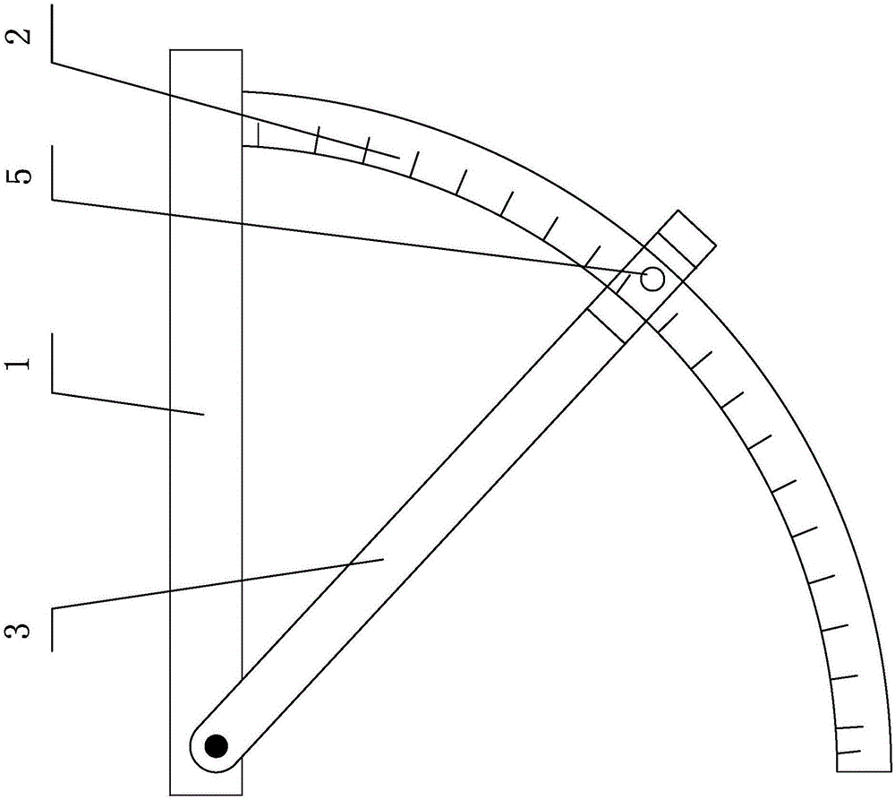
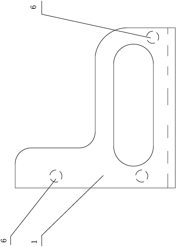
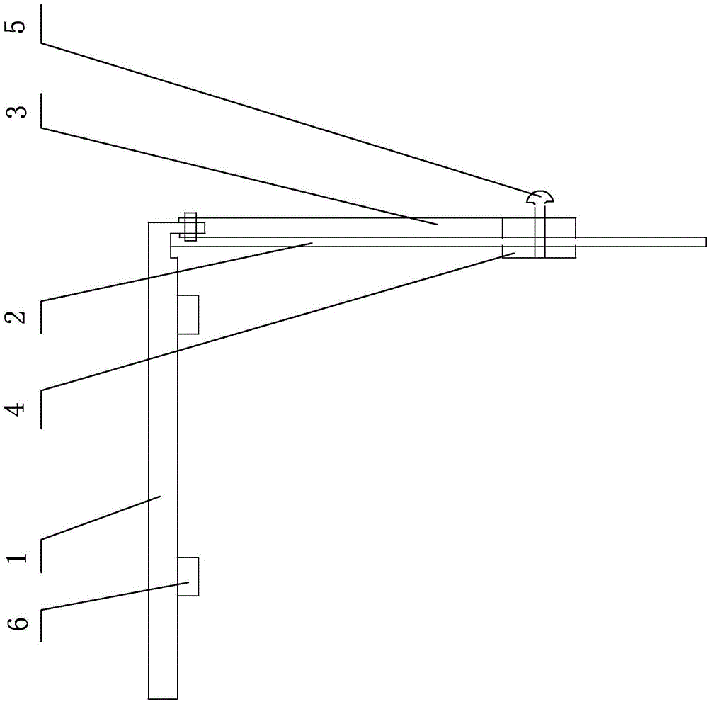
[0033] The cutter is composed of a right-angle base plate 1, an angle ruler 2 and a cutting ruler 3 and other parts.

[0034] The structure of the cutter is that the right-angle substrate 1 is a rectangular plate, and a vertical ruler and a horizontal ruler are formed by incisions on the upper right thereof, and the intersection of the vertical ruler and the horizontal ruler forms a right angle. The position and the inner side of the horizontal ruler position are respectively provided with a pad 6, and the three pads 6 have the same thickness, as figur...


PUM


Abstract

The invention discloses a process method of an angle steel profiling cutter. The process method of the angle steel profiling cutter comprises a manufacturing process of the cutter and a cutting method of the cutter, wherein the manufacturing process comprises the following steps: connecting a right-angled base plate and an angle ruler in two planes vertical to each other, enabling the circular center of the angle ruler to be positioned at a right-angled vertex of the right-angled base plate, hinging one end of a cutting guiding ruler to the right-angled base plate at the circular center of the angle ruler, and enabling the other end of the cutting guiding ruler to be in sliding fit with the angle ruler; the cutting method comprises the following steps: making a cutting main mark, namely a cutting line positioned on the steel surface of one side of angle steel and perpendicular to the limb back, on the limb back of the angle steel, rotating the cutting guiding ruler to the angle ruler to determine the cutting angle, placing the right-angled base plate and the angle ruler on the steel surfaces of the two sides of the angle steel, positioning the right-angled side of the right-angled base plate as a cutting guiding side according to the cutting line, and operating a cutting tool to move along the cutting guiding side and the cutting guiding ruler to cut the two side surfaces of the angle steel. By the process method of the angle steel profiling cutter, the working efficiency is high, the product quality is good, the operating difficulty is low, the cutting error rate is low, and the manufacturing process is simplified.

Description

[0001] Technical field: [0002] The invention relates to a cutting scheme for cutting steel structures and steel products, in particular to a process method of an angle steel profiling cutter. Background technique [0003] In the processing and manufacturing of steel products, small profile processing is the most common. When processing, the following methods are often used: first, set out the small profile. Since the profile has multiple surfaces, when drawing the line, first draw one surface, and then carry out the second surface lofting and drawing. After the drawing of each surface is completed, use the flame Cutting, mechanical sawing and other methods can be processed in one time or multiple times. [0004] Usually, when drawing lines, due to the problem of personnel operation level and the difficulty of drawing lines on multiple sides, etc., the drawing lines are inaccurate; when cutting or sawing at the same time, there are easy errors between the reference line and ...

Claims


Application Information

Patent Timeline
IPC IPC(8): B23D79/00B23Q17/22
CPCB23D79/00B23Q17/22B23Q17/2233
Inventor 刘勇孙高军庄学宇
Owner CHINA 19TH METALLURGICAL FANGCHENGGANG DEVICE STRUCTURES
Features
  • Generate Ideas
  • Intellectual Property
  • Life Sciences
  • Materials
  • Tech Scout
  • Unparalleled Data Quality
  • Higher Quality Content
  • 60% Fewer Hallucinations
Learn More