Novel welding and cutting dual-use device

A dual-purpose device, welding and cutting technology, applied in the direction of auxiliary devices, welding/cutting auxiliary equipment, applications, etc., can solve the problems of affecting the quality of the weld, difficult to guarantee the quality of the weld, inconvenient transportation, etc., to solve the problem of uneven incision and Excessive weld position offset, good electrical conductivity and heat dissipation, and simple structure

Active Publication Date: 2017-05-31
GUANGXI POWER GRID CO LTD NANNING POWER SUPPLY BUREAU
View PDF9 Cites 3 Cited by
  • Summary
  • Abstract
  • Description
  • Claims
  • Application Information

AI Technical Summary

Problems solved by technology

[0002] When welding and cutting round pipes at the construction site, there is no good cutting device, resulting in uneven cuts or inclined cuts. When the pipes are connected, the pipes are not horizontal or the gap between the joints is large or small. Welding It causes a lot of inconvenience and even affects the quality of the weld seam. At the same time, due to the limitation of the station during on-site welding, many welding positions are not easy to be welded, and the quality of the weld seam is difficult to guarantee, especially when welding pressure pipes. Some professional welding and cutting equipment have complex structures, high prices, large volume, inconvenient transportation, and cannot carry out welding and cutting operations on the spot. Large, only its transportation cost is a problem, so a welding and cutting device with simple structure, reliability and portability needs to be developed

Method used


Image

  • Novel welding and cutting dual-use device
  • Novel welding and cutting dual-use device
  • Novel welding and cutting dual-use device

Examples


Embodiment

[0021] In order to make the technical means, creative features, goals and effects achieved by the present invention easy to understand, the present invention will be further described below in conjunction with specific embodiments.

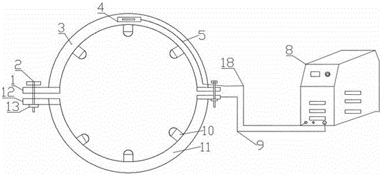
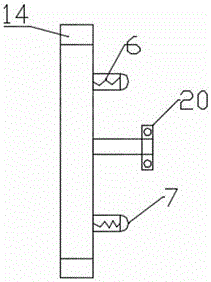
[0022] see figure 1 and figure 2 , the present invention provides a technical solution: a novel dual-purpose device for welding and cutting, including an upper snap ring 3 and a welding and cutting device 8, the model of the welding and cutting device 8 is GUT-40 plasma welding and cutting machine, because GUT-40 The plasma welding and cutting machine not only has superior performance, but also is easy to use and carry. A lower snap ring 11 is provided directly below the upper snap ring 3. At the same time, the lower snap ring 11 and the upper snap ring 3 are symmetrical up and down. On the upper snap ring 3 There are power line grooves 5 and a plurality of conductive devices 10 inside, and springs 6 and balls 7 are arranged inside the conductiv...


PUM

PropertyMeasurementUnit
lengthaaaaaaaaaa

Abstract

The invention discloses a novel welding and cutting dual-use device. The novel welding and cutting dual-use device comprises an upper clamp ring and a plasma welding-cutting machine. A lower clamp ring is arranged under the upper clamp ring, and a welding-cutting gun fixing support is arranged in the upper clamp ring. Power wire slots and six conductive devices are arranged in the upper clamp ring and the lower clamp ring, and springs and balls are arranged in the conductive devices. Extension feet I are arranged on the left side and the right side of the upper clamp ring, and round holes are formed in the extension feet I. Extension feet II are arranged on the left side and the right side of the lower clamp ring, and nuts are welded to the bottoms of the extension feet II. The nuts and the round holes are in central symmetry. The extension feet I are connected with the extension feet II through bolts, and a welding-cutting device is arranged on the right sides of the upper clamp ring and the lower clamp ring. The upper clamp ring and the lower clamp ring are arranged and matched with the welding-cutting gun fixing support, so that weld line deviation is small in the welding process; additionally, the balls in the conductive devices can roll on the surface of a workpiece, so that burns, caused by poor ground in the welding process, on the surface of the workpiece can be reduced, and therefore the novel welding and cutting dual-use device has high practicality.

Description

technical field [0001] The invention relates to welding and cutting, in particular to a novel dual-purpose device for welding and cutting. Background technique [0002] When welding and cutting round pipes at the construction site, there is no good cutting device, resulting in uneven cuts or inclined cuts. When the pipes are connected, the pipes are not horizontal or the gap between the joints is large or small. Welding It causes a lot of inconvenience, and even affects the quality of the weld seam. At the same time, due to the limitation of the station during on-site welding, many welding positions are not easy to be welded, and the quality of the weld seam is difficult to guarantee, especially when welding pressure pipes. Some professional welding and cutting equipment have complex structures, high prices, large volume, inconvenient transportation, and cannot carry out welding and cutting operations on site. Large, only its transportation cost is a problem, so a welding a...

Claims


Application Information

Patent Timeline
Patent Type & Authority Applications(China)
IPC IPC(8): B23K37/02B23K10/00B23K101/06
CPCB23K10/00B23K37/02B23K37/0217B23K2101/06
Inventor 韦孺聪
Owner GUANGXI POWER GRID CO LTD NANNING POWER SUPPLY BUREAU
Why Eureka
Try Eureka