A Compensation Method for End Position of Industrial Robot

An industrial robot, end position technology, applied in manipulators, manufacturing tools, program-controlled manipulators, etc., can solve problems such as difficult program management, complicated robot operation procedures, and increased weight of welding tongs or grinding wheels.

Active Publication Date: 2020-04-07
SHENYANG SIASUN ROBOT & AUTOMATION +1
View PDF4 Cites 0 Cited by
  • Summary
  • Abstract
  • Description
  • Claims
  • Application Information

AI Technical Summary

Problems solved by technology

However, the spring device not only increases the weight of the welding tongs or the grinding wheel, but also increases the cost of the application tool; and the grinding robot needs to prepare different grinding procedures according to the consumption of the grinding wheel to ensure the quality of the grinding, which makes the robot operation procedure complicated , it is also more difficult in terms of program management

Method used


Image

  • A Compensation Method for End Position of Industrial Robot

Examples


Embodiment 1

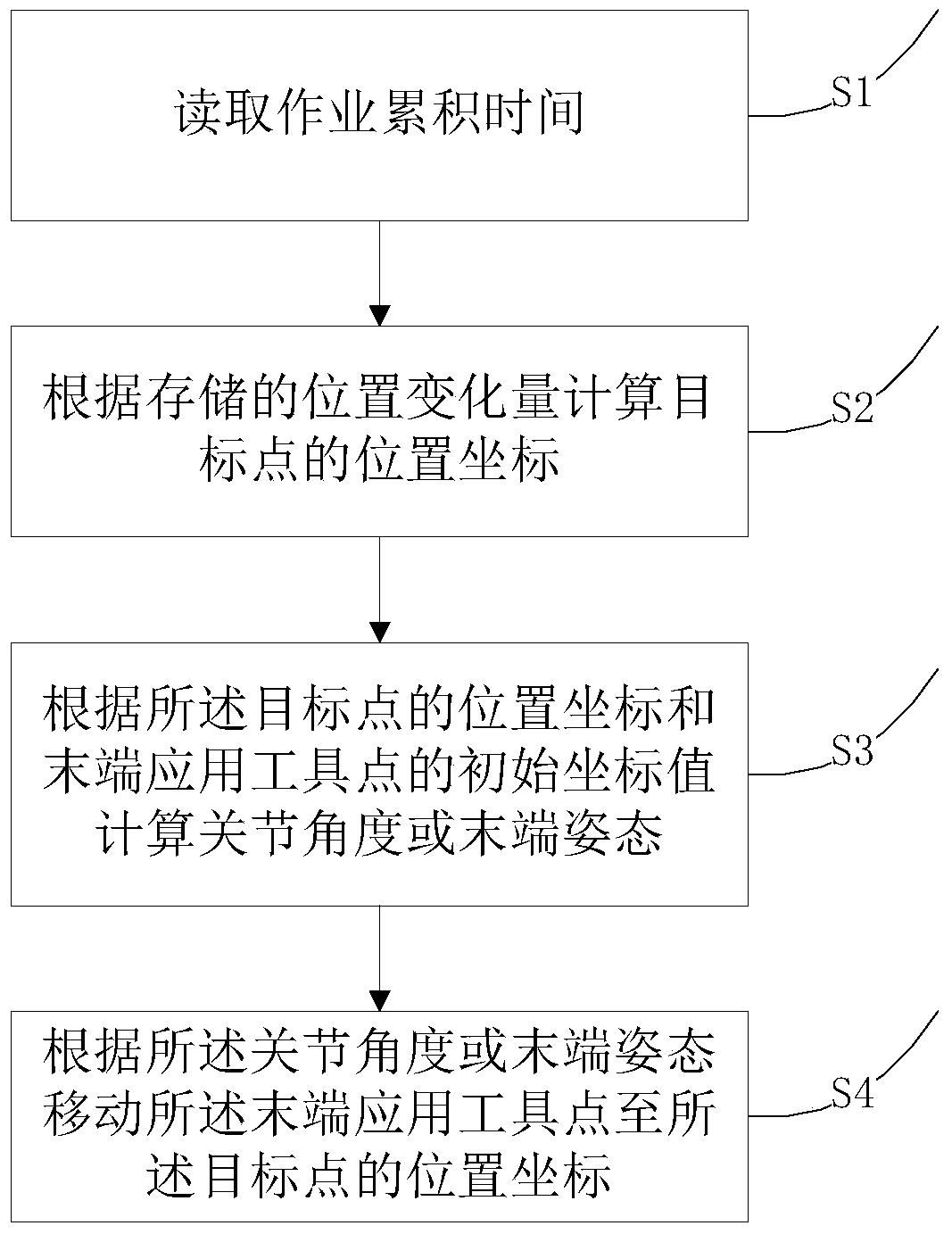
[0029] Embodiment 1 of the present invention provides an industrial robot end position compensation method, including the following steps,

[0030] S1. Accumulated time of reading jobs;

[0031] S2. Calculate the position coordinates of the target point according to the stored position change amount;

[0032] Wherein, the position coordinate formula of described calculation target point is:

[0033] X=xi+x(t);

[0034] Y=yi+y(t);

[0035] Z=zi+z(t);

[0036] Among them, t is the cumulative time of the job; xi, yi, zi are the initial coordinate values ​​of the terminal application tool point; x(t), y(t), z(t) are the terminal application tool point in the x, y, z direction change in wear.

[0037] S3. Calculate joint angles or terminal postures according to the position coordinates of the target point and the initial coordinate values ​​of the terminal application tool point;

[0038] S4. Moving the end application tool point to the position coordinates of the target poin...

Embodiment 2

[0041] Embodiment 2 of the present invention provides an industrial robot end position compensation method, including the following steps,

[0042] S0, call the position point from the saved program data;

[0043] And, after calling the location point from the saved program data, it also includes judging whether the calling location point is a compensation point;

[0044] S1. Accumulated time of reading jobs;

[0045] S2. Calculate the position coordinates of the target point according to the stored position change amount;

[0046] S3. Calculate joint angles or terminal postures according to the position coordinates of the target point and the initial coordinate values ​​of the terminal application tool point;

[0047] S4. Moving the end application tool point to the position coordinates of the target point according to the joint angle or the end posture.

Embodiment 3

[0049] Embodiment 3 of the present invention provides an industrial robot end position compensation method, including the following steps,

[0050] S1. Accumulated time of reading jobs;

[0051] S2. Calculate the position coordinates of the target point according to the stored position change amount;

[0052] S3. Calculate joint angles or terminal postures according to the position coordinates of the target point and the initial coordinate values ​​of the terminal application tool point;

[0053] Wherein, the joint angle is obtained by calculating the inverse transformation of the coordinate values ​​(Xib, Yib, Zib) in the robot base coordinates and the tool coordinate values ​​(X, Y, Z).

[0054] S4. Moving the end application tool point to the position coordinates of the target point according to the joint angle or the end posture.


PUM


Abstract

The invention provides an industrial robot terminal position compensation method. The industrial robot terminal position compensation method comprises the following steps that S1, the operation cumulative time is read; S2, the position coordinate of a target point is calculated according to the stored position variable quantity; S3, the joint angle or the terminal attitude is calculated according to the position coordinate of the target point and the initial coordinate value of a terminal application tool point; and S4, the terminal application tool point is moved to the position coordinate of the target point according to the joint angle or the terminal attitude. According to the industrial robot terminal position compensation method, the robot terminal position can be effectively compensated through the method, the robot terminal position error is decreased, and the high efficiency of a robot application program is achieved.

Description

【Technical field】 [0001] The invention relates to the technical field of industrial robots, in particular to an end position compensation method of an industrial robot. 【Background technique】 [0002] Robot end application tools usually have consumption and wear. For example, the terminal application tool of an electric welding robot is a welding tong, and the electrode of the welding tong is a consumer product, which needs to be replaced regularly according to the number of uses. Due to the consumption of electrodes, the position of robot TCP (TOOLCENTER POINT) will change, and the robot needs to absorb the changes caused by electrode consumption to ensure welding quality. Usually, a spring device that absorbs TCP changes is added to the welding tongs. [0003] The grinding wheel applied at the end of the grinding robot also has wear. In order to absorb the TCP change caused by wear, a spring device will also be installed on the grinding device. However, the spring devic...

Claims


Application Information

Patent Timeline
Patent Type & Authority Patents(China)
IPC IPC(8): B25J9/16
CPCB25J9/1641
Inventor 李学威徐方褚明杰花鹏刘贺张鹏
Owner SHENYANG SIASUN ROBOT & AUTOMATION
Why Eureka
Try Eureka