
Two-step error compensation method for robot

An error compensation and robot technology, applied in the field of robot calibration, can solve the problem of inability to directly compensate geometric parameter errors, and achieve the effect of improving absolute positioning accuracy and reducing position errors.

Active Publication Date: 2020-04-24
GUANGXI UNIV
View PDF14 Cites 12 Cited by
  • Summary
  • Abstract
  • Description
  • Claims
  • Application Information

AI Technical Summary

Problems solved by technology

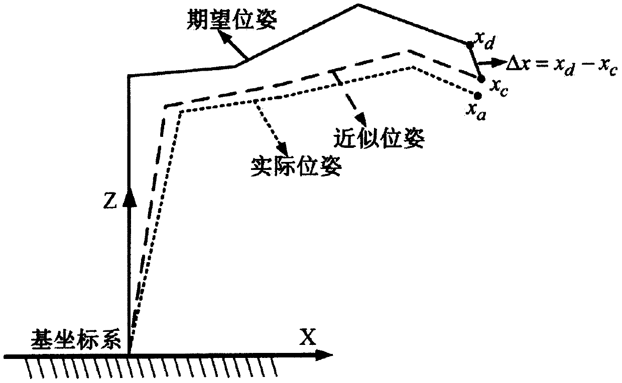
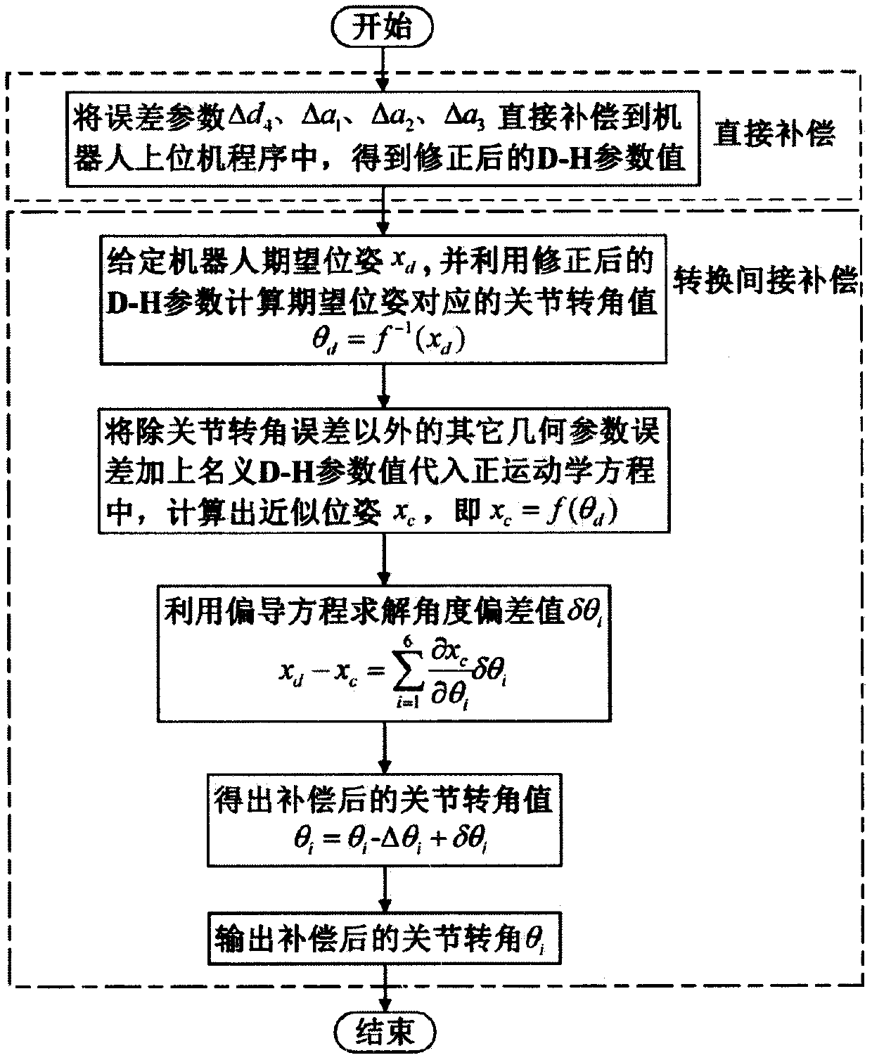
[0006] Aiming at the problem that most robot structures need to meet the Pieper criterion and cannot directly compensate all geometric parameter errors, the present invention proposes a two-step error compensation method, which directly compensates the geometric parameter errors that can be directly compensated to the current D-H configuration parameters of the robot. Convert the remaining errors of other geometric parameters into joint rotation angle compensation values, correct the joint rotation angle values ​​of each joint of the robot, and perform indirect compensation

Method used


Image

  • Two-step error compensation method for robot
  • Two-step error compensation method for robot
  • Two-step error compensation method for robot

Examples


Embodiment Construction

[0032] Further illustrate the present invention below in conjunction with accompanying drawing, a kind of two-step error compensation method for robot that the present invention proposes, comprises the following steps:

[0033] First, establish a robot positioning error model and perform parameter identification:

[0034] In this embodiment, the kinematics model of the Kawasaki RS010NA six-degree-of-freedom industrial robot is established according to the D-H method, and the coordinate system of each joint of the robot is shown in the appendix figure 1 , the D-H modeling method uses four parameters to describe the transformation between adjacent joint coordinate systems. However, when the axes of two adjacent joints are parallel or close to parallel, using four parameters cannot describe the angle of rotation around the y-axis in coordinate system transformation. Therefore, the angle β of rotation around the y-axis is added on the basis of the D-H model to obtain The modified...


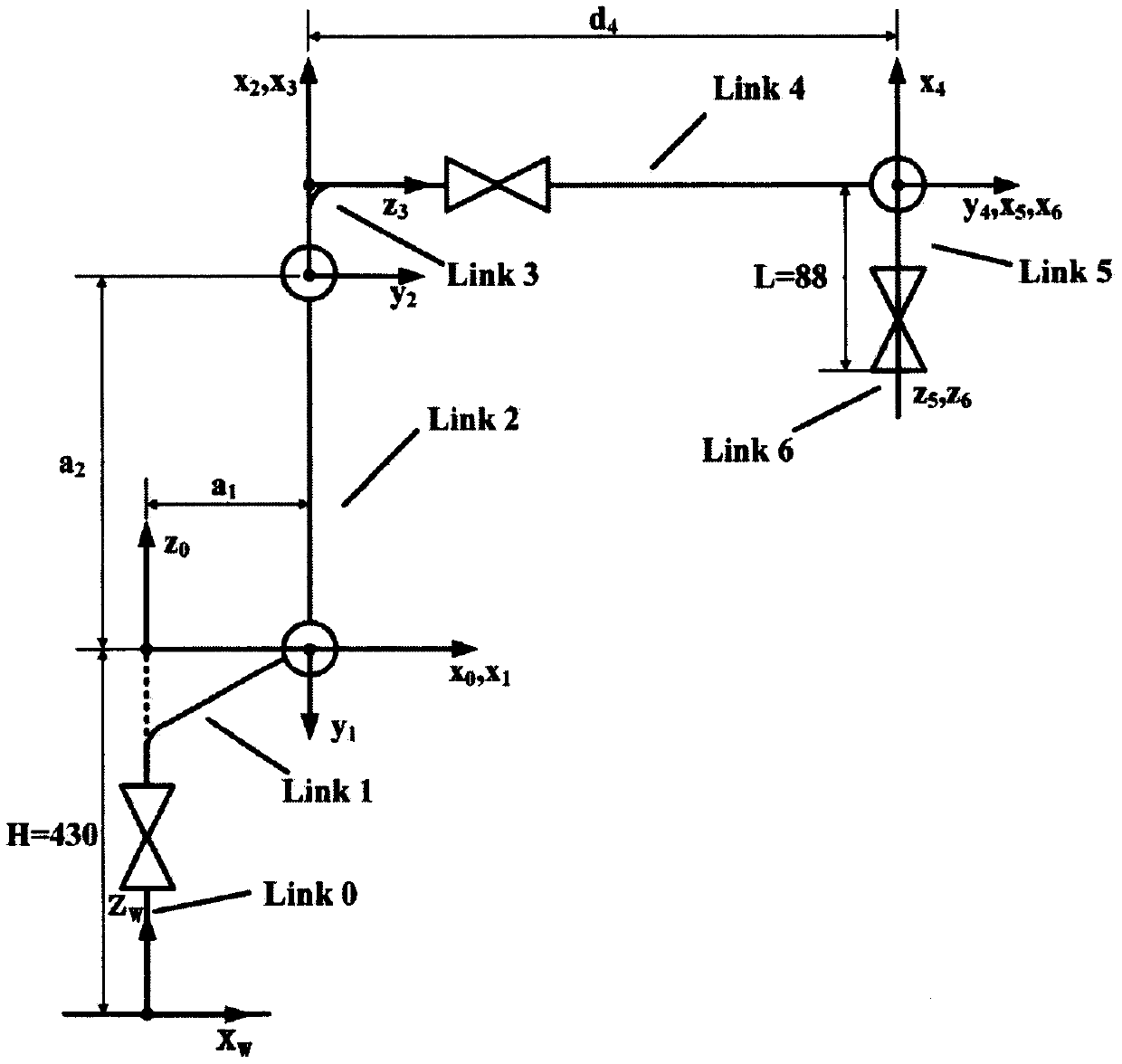
PUM


Abstract

The invention discloses a two-step error compensation method for a robot. The method comprises the steps of: (1) establishing a robot positioning error model based on a corrected D-H method and differential kinematics; (2) solving all geometric parameter errors by utilizing a least squares iteration estimation, and directly compensating the directly compensatable geometric parameter errors into D-H configuration parameters of the robot; and (3) converting the non-directly compensatable geometric parameter errors into a joint rotation angle compensation value, and correcting the rotation anglevalue of each joint of the robot to realize indirect compensation. According to the method, robot error compensation is divided into two steps, direct compensation of geometric parameter errors solvedby a robot inverse kinematics algorithm cannot be affected, and residual geometric parameter errors are indirectly compensated to robot joint rotation angles. According to the method, existing robotinverse kinematics algorithm does not need to be modified, robot tail end position errors can be effectively reduced, robot tail end absolute positioning precision is improved, and the method can be widely applied to the technical field of robot error compensation.

Description

technical field [0001] The invention relates to a two-step error compensation method for a robot, belonging to the technical field of robot calibration. Background technique [0002] In order to enable industrial robots to be applied in a wider range of fields, it is required to have higher positioning accuracy. Repeated positioning accuracy and absolute positioning accuracy are two important indicators to measure the positioning accuracy of industrial robots. At present, most industrial robots have high repetitive positioning accuracy, but their absolute positioning accuracy is difficult to meet the requirements. In traditional manual teaching tasks, only robots are required to have high repetitive positioning accuracy. With the development of the entire industrial field towards automation and intelligence, robots are required to have higher absolute positioning accuracy, and their existing accuracy levels can no longer meet the requirements of certain operations. For this...

Claims


Application Information

Patent Timeline
IPC IPC(8): B25J9/16
CPCB25J9/16B25J9/1628
Inventor 陈琳刘华辉刘吉刚潘海鸿梁旭斌蒲明辉
Owner GUANGXI UNIV
Learn More