
Rear press roller mechanism for cylinder forming of paper bag machine

A paper bag machine and tube forming technology, which is used in paper making, bag making operations, paper/cardboard containers, etc., can solve the problems of different pressures, indentation on the surface of paper bags, etc., and achieve the effect of easy maintenance and inspection.

Active Publication Date: 2017-05-31
温州巨凯机械有限公司
View PDF7 Cites 3 Cited by
  • Summary
  • Abstract
  • Description
  • Claims
  • Application Information

AI Technical Summary

Problems solved by technology

However, the pressure wheel mechanism after the traditional handbag is formed into a tube is often conveyed by two sets of upper and lower rollers. Since the thickness of different paper bags is also inconsistent, in order to ensure the compatibility of the equipment, the general upper and lower rollers are made of rubber wheels. The elastic deformation of the rubber wheel itself satisfies the conveyance of paper bags with different thicknesses. However, when conveying paper bags with thicker thickness and folded edges, the pressure received by the paper bags is also different due to the thickness, which is easy to cause pressure on the surface of the paper bag. scars

Method used


Image

  • Rear press roller mechanism for cylinder forming of paper bag machine
  • Rear press roller mechanism for cylinder forming of paper bag machine
  • Rear press roller mechanism for cylinder forming of paper bag machine

Examples


Embodiment Construction

[0024] The specific implementation manners of the present invention will be further described in detail below in conjunction with the accompanying drawings and embodiments. The following examples are used to illustrate the present invention, but are not intended to limit the scope of the present invention.

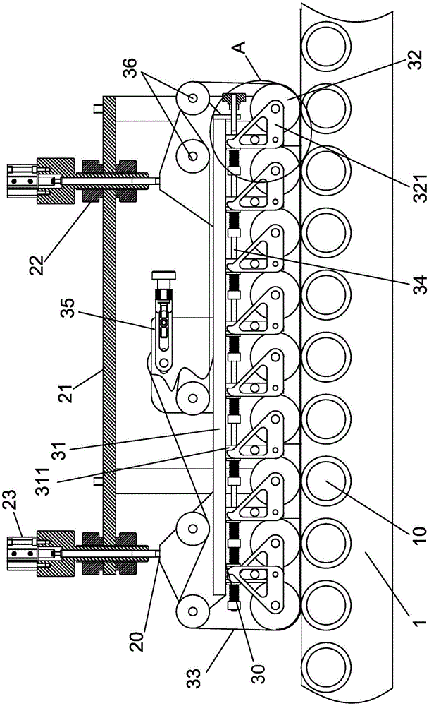
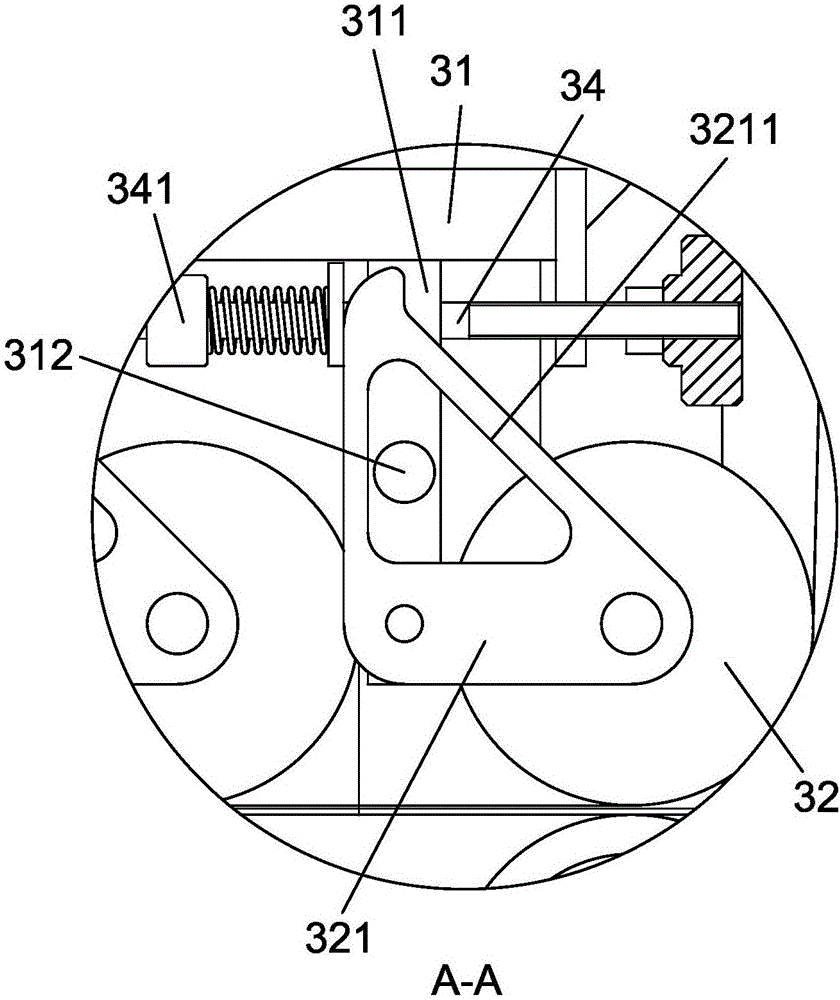
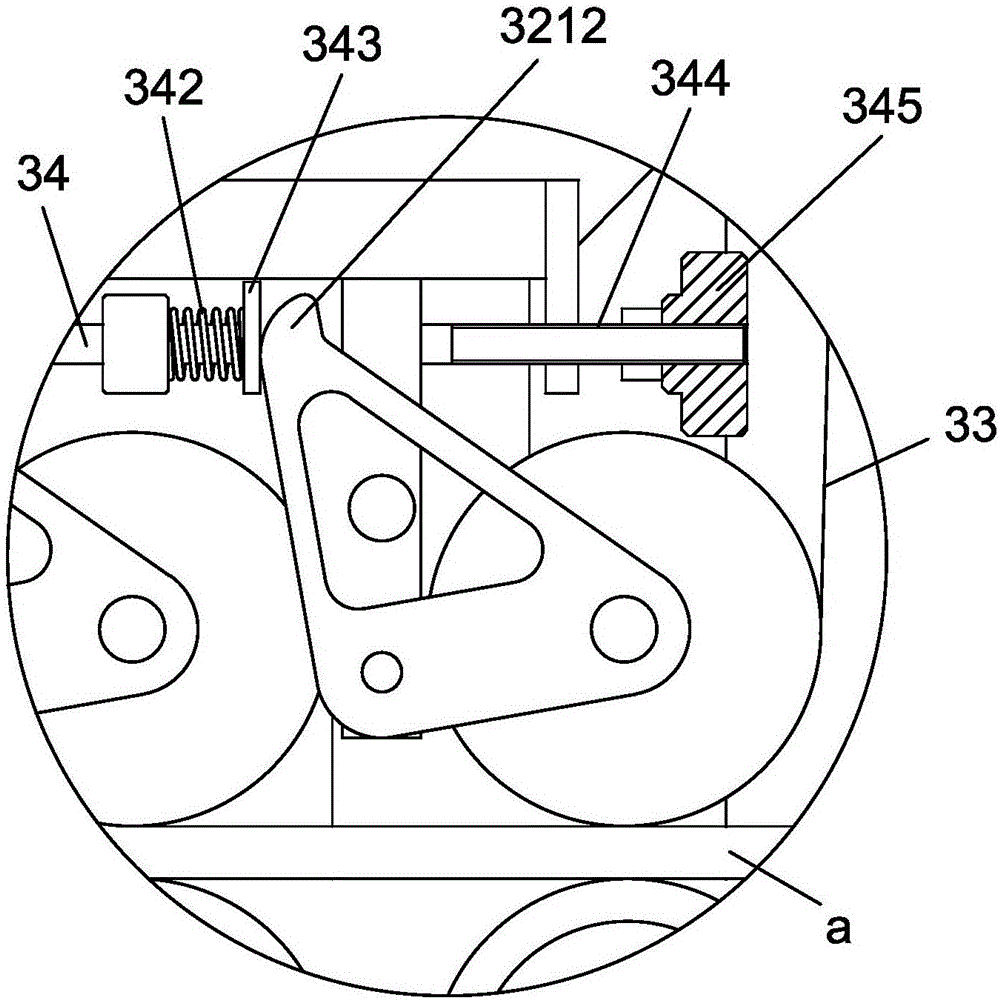
[0025] refer to Figure 1 to Figure 3 ,Such as Figure 1 to Figure 3 The roller press mechanism after the paper bag machine is formed into a cylinder includes a frame 1 on which several groups of lower rollers 10 are arranged, and an upper roller conveying mechanism 20 is arranged above the lower rollers 10. The above-mentioned roller conveying mechanism 20 includes a crossbeam 21 fixed on the frame 1, and the crossbeam 21 is provided with an adjustable upper roller module 30, and the upper roller module 30 includes a mounting plate 31, and the mounting plate 31. A number of upper rollers 32 are arranged at the bottom toward the conveying direction, which are one-to-one ...


PUM


Abstract

The invention provides a rear press roller mechanism for cylinder forming of a paper bag machine. The rear press roller mechanism comprises a rack; multiple sets of lower rolling shafts are arranged on the rack; and an upper roller conveying mechanism is arranged above the lower rolling shaft. The upper roller conveying mechanism comprises a crossbeam fixed on the rack; an upper roller module which can be adjusted in height is arranged on the crossbeam and comprises a mounting plate; a plurality of upper rollers which are in one-to-one tangency with the lower rolling shafts and can independently and automatically adjust the size of the gap between the lower rolling shafts according to the thicknesses of conveyed paper bags are arranged at the bottom of the mounting plate in the conveying direction; and the upper roller module further comprises a flat belt which is tensioned among the upper rollers and used for conveying the paper bags. Each upper roller can swing independently so that when paper bags pass, the upper rollers can back up and swing upward in time and can tightly press the paper bags and supply friction force for the paper bags, and combined with the flat belt to convey, the paper bags can be conveyed more stably and fitly. By arranging an adjustable cylinder, the height of the upper roller module can be quickly adjusted, maintenance and check are convenient, and the prepressing intensity of each upper roller can be adjusted.

Description

technical field [0001] The invention relates to portable paper bag processing equipment, in particular to a pressure wheel mechanism after the paper bag machine is formed into a tube. Background technique [0002] Today, the handbag forming machine has realized the automatic mass production of handbags, among which folding into a tube, pasting the bottom and pulling the bottom are the main processes of the handbag forming machine. The traditional handbag forming machine usually arranges the forming devices in the order of the forward direction of the bag body, such as feeding device, flanging tube device, bottom paste device, bottom pulling device, etc. However, the pressure wheel mechanism after the traditional handbag is formed into a tube is often conveyed by two sets of upper and lower rollers. Since the thickness of different paper bags is also inconsistent, in order to ensure the compatibility of the equipment, the general upper and lower rollers are made of rubber whe...

Claims


Application Information

Patent Timeline
IPC IPC(8): B31B70/94
Inventor 蔡锦丹刘德明朱伯乐
Owner 温州巨凯机械有限公司
Learn More