Magnetic-levitation train and hydraulic guide device and method of magnetic-levitation train

A technology for maglev trains and guiding devices, applied in electric vehicles, vehicle components, transportation and packaging, etc., can solve problems such as affecting train control, reducing the stability and ride comfort of maglev trains, and incompressible hydraulic oil, and improving the Stability and ride comfort, solving the problem of incompressibility of liquid media alone, avoiding adverse effects

Active Publication Date: 2017-05-31
ZHUZHOU ELECTRIC LOCOMOTIVE CO LTD
View PDF5 Cites 13 Cited by
  • Summary
  • Abstract
  • Description
  • Claims
  • Application Information

AI Technical Summary

Problems solved by technology

But there are the following deficiencies: the main purpose of the guide mechanism is to arrange the suspension frame units radially along the curve to ensure that the vehicle passes through the curve smoothly, and the guide mechanism is not expected to act on the straight road section.
However, due to the incompressible characteristics of hydraulic oil, the slight lateral movement of any hydraulic cylinder will be quickly fed back to another hydraulic cylinder in the same group, which will cause lateral interference of one or three slides (or four or six slides) Displacement factor coupling, this undesired lateral motion coupling, will affect train control and reduce the stability and ride comfort of maglev trains

Method used


Image

  • Magnetic-levitation train and hydraulic guide device and method of magnetic-levitation train
  • Magnetic-levitation train and hydraulic guide device and method of magnetic-levitation train
  • Magnetic-levitation train and hydraulic guide device and method of magnetic-levitation train

Examples


Embodiment Construction

[0039] The present invention will be described in detail below with reference to the accompanying drawings and examples. It should be noted that, in the case of no conflict, the embodiments of the present invention and the features in the embodiments can be combined with each other. For the convenience of description, if the words "up", "down", "left" and "right" appear in the following, it only means that the directions of up, down, left and right are consistent with the drawings themselves, and do not limit the structure.

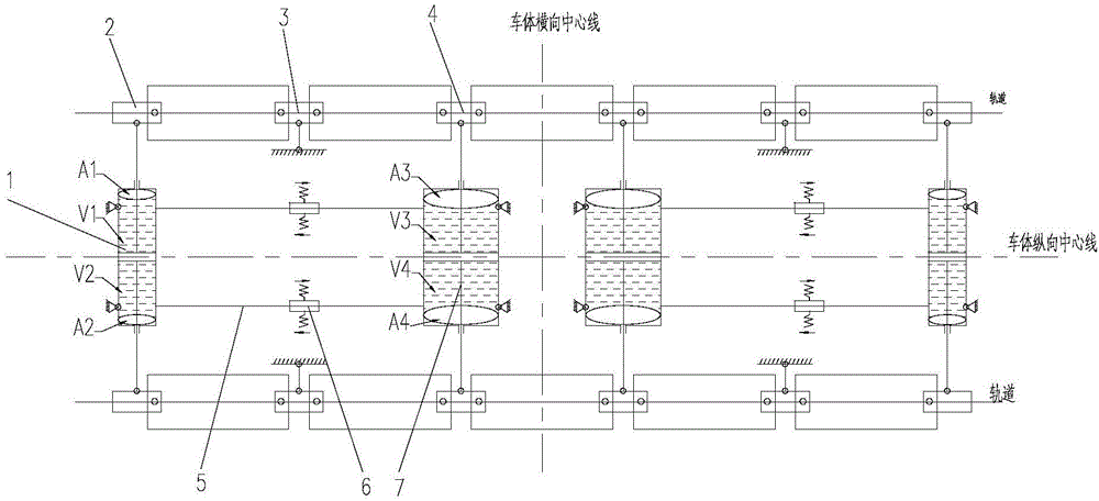
[0040] A hydraulic guide device for a maglev train, such as image 3 As shown, it mainly consists of the first hydraulic cylinder 1, one-position sliding table device 2, two sets of symmetrically arranged differential pressure valve units 6, two sets of symmetrically arranged hydraulic pipelines 5, three-position sliding table device 4, and the second hydraulic cylinder 7 composition. Wherein, the piston rods at both ends of the first hydraulic cylinder...


PUM


Abstract

The invention discloses a magnetic-levitation train and a hydraulic guide device and method of the magnetic-levitation train. The hydraulic guide device comprises two groups of first-position sliding platform devices, two groups of second-position sliding platform devices and two groups of third-position sliding platform devices, which are sequentially connected in series and are movably connected; the two groups of first-position sliding platform devices are movably connected through a first hydraulic oil cylinder; the two groups of third-position sliding platform devices are movably connected through a second hydraulic oil cylinder; the first hydraulic oil cylinder and the second hydraulic oil cylinder are buffering type hydraulic oil cylinders with a double-rod piston structure; the first hydraulic oil cylinder and the second hydraulic oil cylinder are communicated through a hydraulic pipeline with a differential pressure valve unit; the differential pressure valve unit is used for adjusting pressure difference between the first hydraulic oil cylinder and the second hydraulic oil cylinder. According to the magnetic-levitation train disclosed by the invention, a levitation module can be distributed along the radial direction when the magnetic-levitation train passes through a curve section, so that mutual coupling of small-range transverse movement of a first-position sliding platform and a third-position sliding platform on linear rails can be effectively prevented; bad influences on the operation stability of the train are avoided, and the stability and sitting comfort of the magnetic-levitation train are improved.

Description

technical field [0001] The invention relates to a maglev train, a hydraulic guiding device and a guiding method thereof, and belongs to the field of maglev train vehicles. Background technique [0002] There are mainly two structures in the design of the guide device of the existing medium-low speed maglev train: mechanical guide structure and hydraulic guide structure. [0003] Mechanically guided structures such as figure 1 As shown, the main structure includes two sets of rotating arms, two sets of longitudinal tie rods and four sets of transverse tie rods. The longitudinal tie rods are connected to the rotating arm, and the rotating arm is fixed to the car body to form a realizable parallelogram frame. Four sets of transverse tie rods are connected to the modules in the suspension frame unit for assembly. When the train passes through the curve, the module slides relative to the car body, driving the transverse tie rod and the parallelogram structure to move, so that t...

Claims


Application Information

Patent Timeline
Patent Type & Authority Applications(China)
IPC IPC(8): B60L13/04
CPCB60L13/04
Inventor 李茂春李小燕陈喜红陶功安晋军辉李冠军汪林峰贺世忠朱向阳何永川孙志明谭云周鹤
Owner ZHUZHOU ELECTRIC LOCOMOTIVE CO LTD
Why Eureka
Try Eureka