Manual relief device for track vehicle parking brake cylinders

A technology for parking brakes and rail vehicles, which is applied in the field of rail transit vehicles. It can solve the problems of manual relief devices being difficult to pull and difficult to operate, and achieve the effects of improving work efficiency, reducing operation difficulty, and reducing pulling force

Inactive Publication Date: 2017-05-31
CRRC QINGDAO SIFANG ROLLING STOCK RES INST
View PDF6 Cites 12 Cited by
  • Summary
  • Abstract
  • Description
  • Claims
  • Application Information

AI Technical Summary

Problems solved by technology

[0006] Aiming at the problems that the current manual release device is difficult to pull and difficult to op

Method used


Image

  • Manual relief device for track vehicle parking brake cylinders
  • Manual relief device for track vehicle parking brake cylinders

Examples


specific Embodiment approach

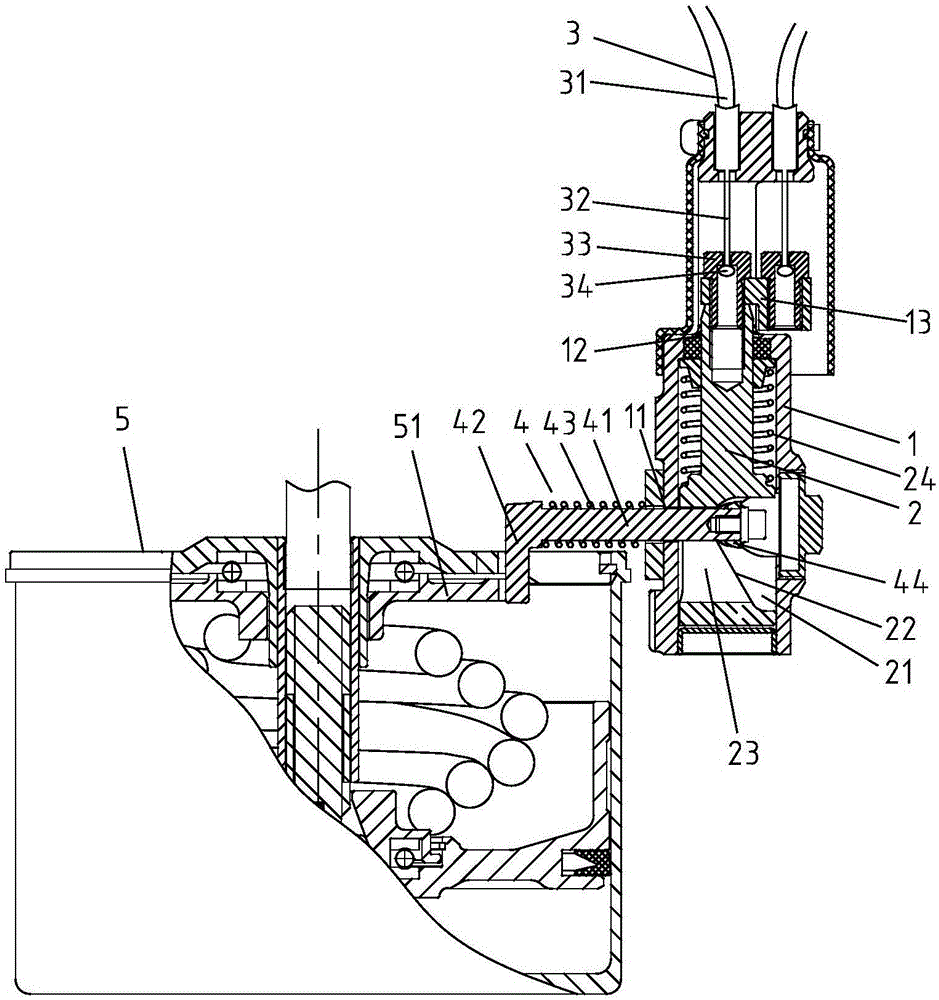
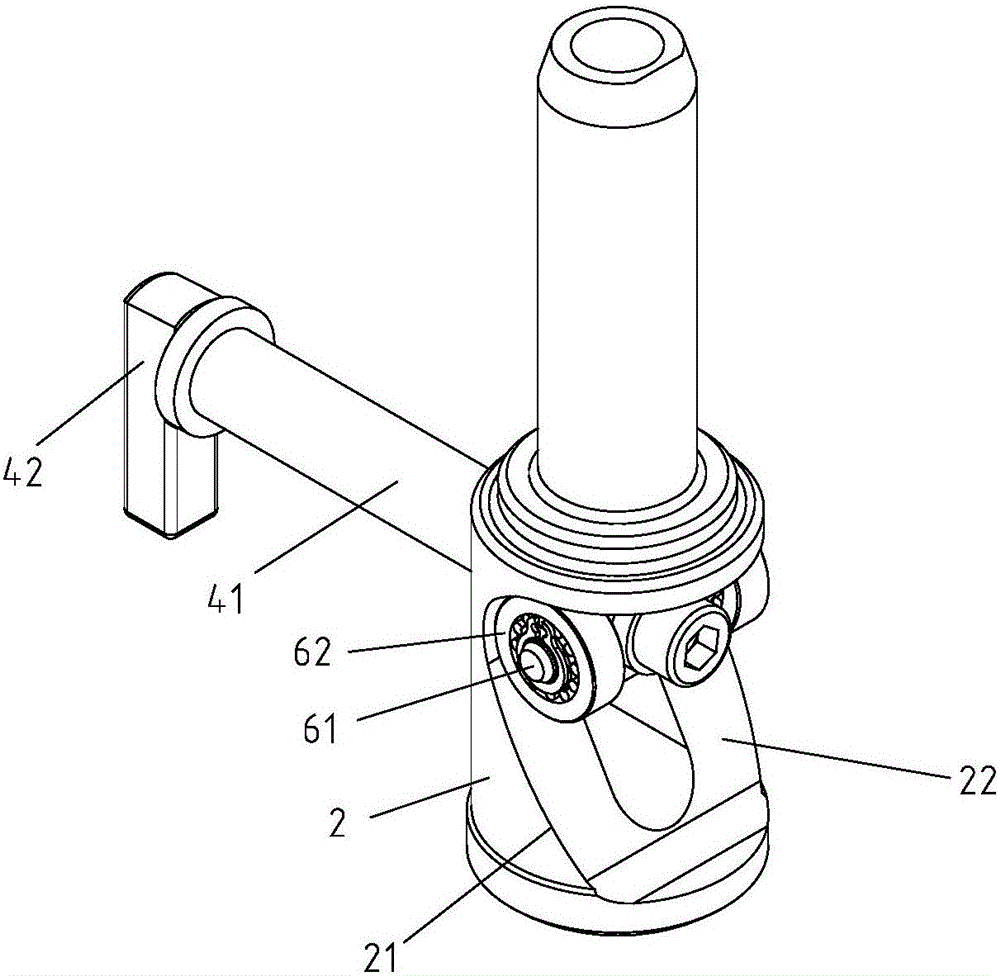
[0029] Such as Figures 1 to 2 As shown, the manual release device for the parking brake cylinder of a rail vehicle includes a release support seat 1, a pull rod 2 slidably installed in the inner cavity provided by the release support seat 1, a release cable 3 that drives the pull rod 2 to slide, and a release cable 3 that is slidably installed in the relief support seat 1. The relief pin 4 in the mounting hole 11 provided on the side wall of the supporting seat 1.

[0030] The parking brake cylinder includes a brake cylinder and a parking cylinder installed on the brake cylinder. The relief support seat 1 is located on one side of the parking cylinder and can be fixed on the brake cylinder, on the parking cylinder or on the rail vehicle frame, etc. s position.

[0031] The side wall of the pull rod 2 is provided with a drive groove 21 , and the groove bottom of the drive groove 21 is a guide surface 22 inclined relative to the axis of the pull rod 2 . The guide surface 22 f...


PUM


Abstract

Disclosed is a manual relief device for track vehicle parking brake cylinders. The manual relief device comprises a relief support seat, a pull rod slidably mounted in the cavity arranged in the relief support seat, relief stay ropes driving the pull rod to slide and a relief pin slidably mounted in a mounting hole arranged in the side wall of the relief support seat; motion direction of the relief pin is changed through a slanting wedge structure formed by a guiding surface tilting in a driving groove, tensile force needed in manual pull relief is reduced, difficulty in operation of manual relief is lowered, and operation efficiency is improved; the pull rod and a relief rod are perpendicular to each other, so that change in motion direction of the relief pin is maximized; a reset spring is mounted on the relief rod, so that the relief rod can be reset after completion of manual relief, a ratchet wheel of a parking cylinder is clamped, and the parking cylinder can be reset when a vehicle restores brake pressure. The reset spring is mounted on the pull rod, so that the pull rod and the relief pin can be reset more rapidly.

Description

technical field [0001] The invention relates to the field of rail vehicles, in particular to a manual release device for a parking brake cylinder of a rail vehicle. Background technique [0002] The disc brake caliper device of a rail transit vehicle usually includes a wheel-mounted brake caliper unit, an axle-mounted brake caliper unit, and a parking brake caliper unit. The parking brake caliper unit usually adopts a spring energy storage type parking cylinder. During the normal operation of the vehicle, the compressed air in the brake pipeline is always charged into the parking cylinder to compress the spring to make it in a relieved state. When the train applies the parking brake or emergency When braking, the compressed air in the parking cylinder is emptied. In the absence of wind, the manual release device is required to release the parking brake. After manual release, the manual release device automatically resets under the action of the return spring inside the manua...

Claims


Application Information

Patent Timeline
IPC IPC(8): B61H13/02
CPCB61H13/02
Inventor 徐少亭覃立伟黄士伟王震刁有彬
Owner CRRC QINGDAO SIFANG ROLLING STOCK RES INST
Why Eureka
Try Eureka