
Flapping wing airship

An airship and fin technology, applied in the field of flapping airships, can solve the problems of restricting airships, low propeller efficiency, and high price.

Inactive Publication Date: 2017-05-31
南京柯尔航空科技有限公司
View PDF8 Cites 2 Cited by
  • Summary
  • Abstract
  • Description
  • Claims
  • Application Information

AI Technical Summary

Problems solved by technology

[0003] Traditional airships are filled with helium or other lighter-than-air gases (mainly helium) in the airbag to make the airship generate lift and take off, and the airship is controlled by filling or extracting air into the auxiliary airbag. These The characteristics make the production of airships completely dependent on the supply of helium. Helium is a rare strategic resource with a small output and a very expensive price, which cannot meet the needs of mass production and use of airships. Helium requires a large number of special equipment, including transportation, Cooling, storage, purification and other equipment need to be equipped with relevant professional and technical personnel, and the cost of use is expensive. In addition, the huge airbag will be out of control due to sudden strong winds, and accidents will occur. Due to the above factors, the development and wide application of airships are limited. use
[0004] Most airships at this stage are driven by propellers, and the driving efficiency of propellers is not high, especially in the adjacent space, due to the thin air, the efficiency of propellers is very low, while the efficiency of double flapping wings will be much higher

Method used


Image

  • Flapping wing airship
  • Flapping wing airship
  • Flapping wing airship

Examples


Embodiment 1

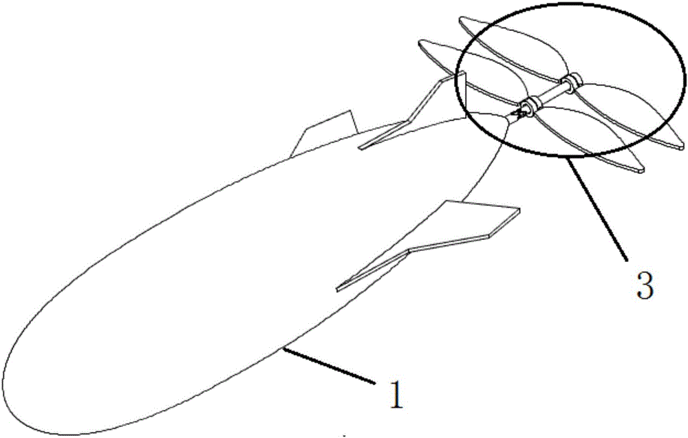
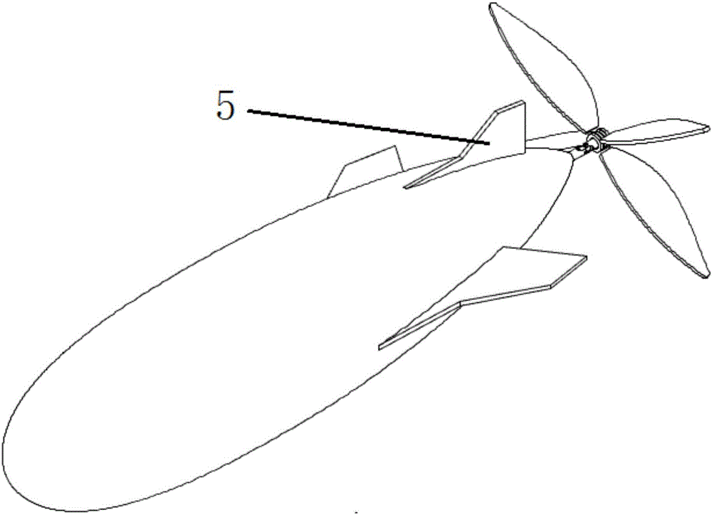
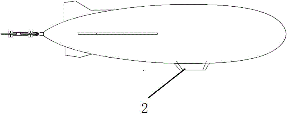
[0033] combine figure 1 , image 3 , Figure 4 and Figure 5 , a flapping-wing airship of the present invention comprises an airbag 1, an auxiliary airbag 1, a pod 2, a double flapping-wing mechanism 3, a tail boom 4, an empennage 5, a rudder and an elevator, and the outer surface of the airbag 1 is respectively provided with a pod 2, Tail boom 4, empennage 5, rudder and elevator; auxiliary airbag 1 is located in airbag 1; pod 2 is located at the bottom of airbag 1; tail boom 4 is located at the tail of airbag 1; double flapping wing mechanism 3 is arranged on tail boom 4; The flapping wing mechanism 3 comprises the flapping wing blade 6, the root shaft 7 and the universal joint 8; the root shaft 7 and the tail rod 4 are connected by the universal joint 8; the flapping wing blade 6 is provided with a ring sleeve 9; the flapping wing blade 6 passes through the ring sleeve 9 is connected with root shaft 7; empennage 5, rudder and elevator are positioned at the rear portion of...

Embodiment 2

[0041] combine figure 2 , image 3 , Figure 6 and Figure 7 , a flapping-wing airship of the present invention comprises an airbag 1, an auxiliary airbag 1, a pod 2, a double flapping-wing mechanism 3, a tail boom 4, an empennage 5, a rudder and an elevator, and the outer surface of the airbag 1 is respectively provided with a pod 2, Tail boom 4, empennage 5, rudder and elevator; auxiliary airbag 1 is located in airbag 1; pod 2 is located at the bottom of airbag 1; tail boom 4 is located at the tail of airbag 1; double flapping wing mechanism 3 is arranged on tail boom 4; The flapping wing mechanism 3 comprises the flapping wing blade 6, the root shaft 7 and the universal joint 8; the root shaft 7 and the tail rod 4 are connected by the universal joint 8; the flapping wing blade 6 is provided with a ring sleeve 9; the flapping wing blade 6 passes through the ring sleeve 9 is connected with root shaft 7; empennage 5, rudder and elevator are positioned at the rear portion o...

Embodiment 3

[0049] combine Figure 4 and Figure 8 , a flapping-wing airship of the present invention comprises an airbag 1, an auxiliary airbag 1, a pod 2, a double flapping-wing mechanism 3, a tail boom 4, an empennage 5, a rudder and an elevator, and the outer surface of the airbag 1 is respectively provided with a pod 2, Tail boom 4, empennage 5, rudder and elevator; auxiliary airbag 1 is located in airbag 1; pod 2 is located at the bottom of airbag 1; tail boom 4 is located at the tail of airbag 1; double flapping wing mechanism 3 is arranged on tail boom 4; The flapping wing mechanism 3 comprises the flapping wing blade 6, the root shaft 7 and the universal joint 8; the root shaft 7 and the tail rod 4 are connected by the universal joint 8; the flapping wing blade 6 is provided with a ring sleeve 9; the flapping wing blade 6 passes through the ring sleeve 9 is connected with root shaft 7; empennage 5, rudder and elevator are positioned at the rear portion of airbag 1. Double flapp...


PUM


Abstract

The invention relates to a flapping wing airship. The flapping wing airship comprises an gasbag, an auxiliary gasbag, a pod, a double-flapping wing mechanism, a tail rod, a tail wing, a rudder and an elevator, wherein the outer surface of the gasbag is provided with the pod, the tail rod, the tail wing, the rudder and the elevator; the auxiliary gasbag is located in the gasbag; the pos is located at the bottom of the gasbag; the tail rod is located at the tail part of the gasbag; the double-flapping wing mechanism is arranged on the tail rod; the double-flapping wing mechanism comprises flapping wing pieces, a root part shaft and a cardan joint; the root part shaft is connected to the tail rod through the cardan joint. Through the adoption of the structure, the flapping wings of the double-flapping wing mechanism can change the sizes of incidence angles of the flapping wings along the rotation of the root part shaft, and the direction in actual flying can be adjusted more freely. In addition, the double-flapping wing mechanism can achieve changing of drive angles through the cardan joint, thus the flapping wing airship can change flight angles more freely and conveniently, movements of pitching, veering and the like of the airship can be quickly achieved, and the flight efficiency of the flapping wing airship is sharply improved.

Description

technical field [0001] The invention relates to the field of aircraft, in particular to a flapping-wing airship. Background technique [0002] An airship is an aircraft that uses a gas lighter than air to provide lift. [0003] Traditional airships are filled with helium or other lighter-than-air gases (mainly helium) in the airbag to make the airship generate lift and take off, and the airship is controlled by filling or extracting air into the auxiliary airbag. These The characteristics make the production of airships completely dependent on the supply of helium. Helium is a rare strategic resource with a small output and a very expensive price, which cannot meet the needs of mass production and use of airships. Helium requires a large number of special equipment, including transportation, Cooling, storage, purification and other equipment need to be equipped with relevant professional and technical personnel, and the cost of use is expensive. In addition, the huge airbag...

Claims


Application Information

Patent Timeline
IPC IPC(8): B64B1/24
CPCB64B1/24
Inventor 杨思强汪俊王波蔺靓于传稳
Owner 南京柯尔航空科技有限公司
Learn More