
Film wrapping machine

A film-wrapping and film-covering technology, applied in the field of film-wrapping machines, can solve the problem that the film-wrapping machine is not easy to move, and achieve the effect of small size, simple operation and convenient movement

Active Publication Date: 2017-05-31
LIUZHOU YUHUA TECH
View PDF6 Cites 7 Cited by
  • Summary
  • Abstract
  • Description
  • Claims
  • Application Information

AI Technical Summary

Problems solved by technology

[0003] The purpose of the present invention is to provide a film wrapping machine, the technical problem to be solved is: the film wrapping machine is not easy to move, and can work in the field

Method used

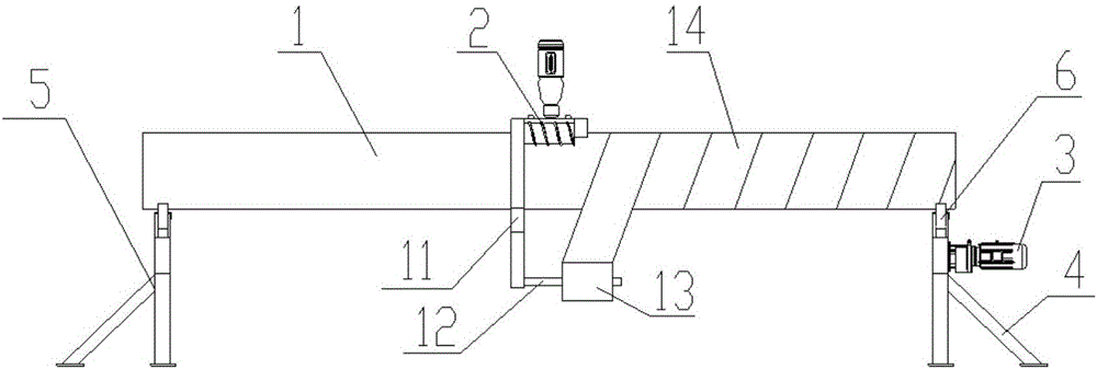
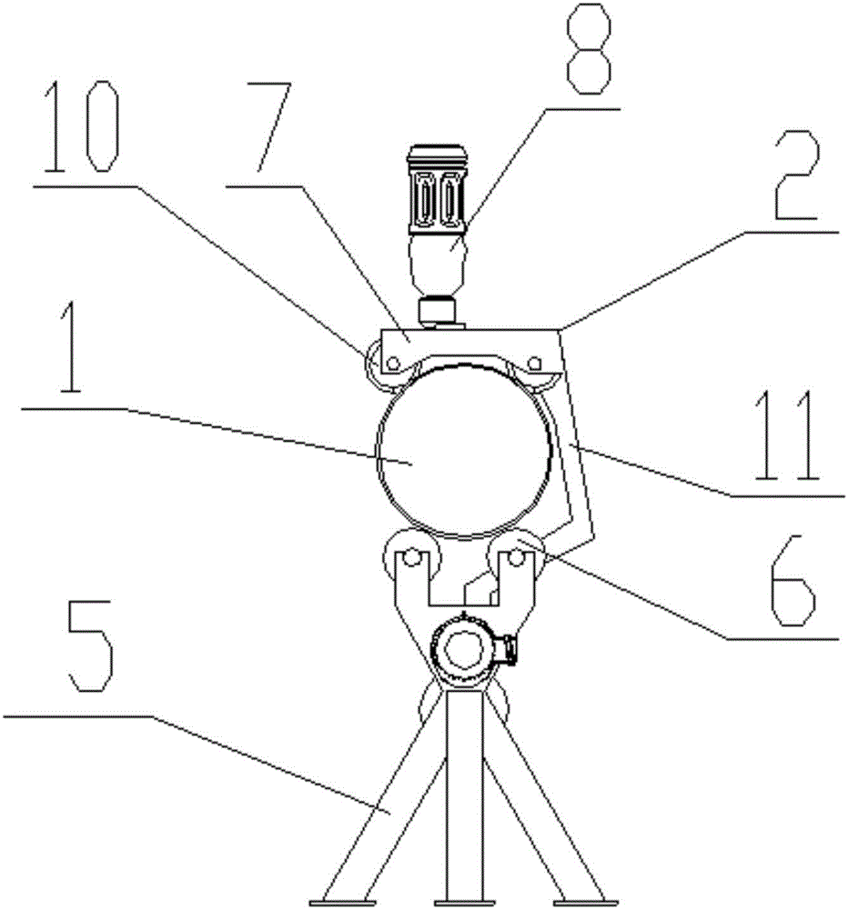
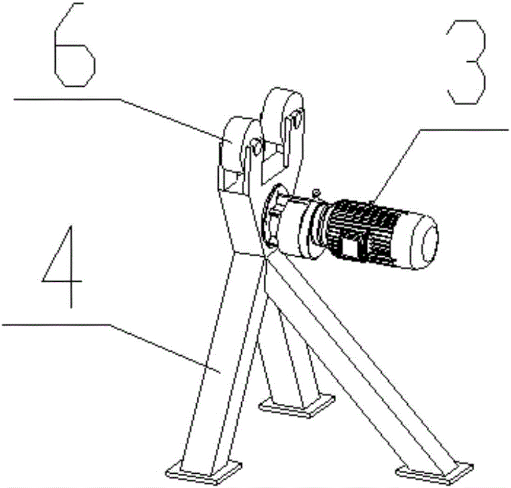

Image

  • Film wrapping machine
  • Film wrapping machine
  • Film wrapping machine

Examples


Embodiment Construction

[0021] The principles and features of the present invention are described below in conjunction with the accompanying drawings, and the examples given are only used to explain the present invention, and are not intended to limit the scope of the present invention.

[0022] Such as Figure 1 to Figure 3 As shown, a film wrapping machine includes a pipe 1, a cover film assembly 2 and a motor 3, and the two sides of the lower end of the pipe 1 are respectively provided with a first support 4 and a second support 5, and the first support 4 and the second support The upper ends of the two brackets 5 are provided with flat rollers 6, and the first bracket 4 and the second bracket 5 support the rolling of the pipe 1 through the flat rollers 6; the cover film assembly 2 is movably placed on the pipe 1 The upper end of the motor 3 is placed on the first support 4, and the output shaft of the motor 3 drives the flat roller 6 on the first support 4 to rotate.

[0023] In the above embodi...


PUM


Abstract

The invention relates to a film wrapping machine which comprises a pipe, a film covering component and a motor. A first support and a second support are arranged on two sides of the lower end of the pipe respectively, a flat roller is arranged at the upper end of each of the first support and the second support, and each of the first support and the second support supports the pipe to roll through the flat rollers; the film covering component is movably arranged at the upper end of the pipe, the motor is arranged on the first support, and an output shaft of the motor drives the flat roller on the first support to rotate. Compared with the prior art, the film wrapping machine has the advantages of small size, convenience in moving and simplicity in operation.

Description

technical field [0001] The invention relates to a film wrapping machine. Background technique [0002] The 201410776722.6 invention relates to a film wrapping machine, which includes a conveying device, a film releasing device on the left and right sides, a vertical clamping welding device, an edge positioning device and a workpiece lifting device. The workpiece tray with the workpiece is placed on the conveying device, left and right The symmetrical left and right film release devices are arranged on both sides of the conveying device. The machine table of the conveying device has a first suction port and a second suction port. The workpiece to be filmed moves forward under the drive of the conveying device. When the welding device is clamped vertically, the vertical clamping welding device welds and divides the film, so that the film is wrapped on the workpiece in a cylindrical shape. When the workpiece passes through the first air outlet, the first air outlet pumps air to...

Claims


Application Information

Patent Timeline
Patent Type & Authority Applications(China)
IPC IPC(8): B65B11/04
CPCB65B11/04
Inventor 班惠辉
Owner LIUZHOU YUHUA TECH
Learn More