Convenient-to-mount and low-energy-consumption antiskid type belt conveyor roller

It is a technology with convenient installation and low energy consumption. It is applied in the direction of conveyor objects, transportation and packaging, and rollers. It can solve the problems of cumbersome welding and production of large iron plates, large loads driven by motors, and heavy rollers. It is not easy to drive The effect of slipping, driving load reduction, and not easy to deform

Inactive Publication Date: 2017-05-31
NANTONG UNION MACHINERY ELECTRONTCS TECH CO LTD
View PDF9 Cites 2 Cited by
  • Summary
  • Abstract
  • Description
  • Claims
  • Application Information

AI Technical Summary

Problems solved by technology

[0002] Belt conveyors are used to transport various materials. The rollers of existing belt conveyors are made of iron plates, so they are quite heavy
At the same time, the rolling process of large iron plates and the later welding production are quite cumbersome
Since most of the welding is drawn welding, the drawing welding of the plate is prone to severe welding deformation due to local heating, and the requirements for welding process are relatively high.
Installation and processing are inconvenient. Due to the heavy weight of the drum, the motor drives a large load, which consumes more electric energy.
In addition, when transferring more objects, the belt will slip along the surface of the drum, which will affect the transmission of materials

Method used


Image

  • Convenient-to-mount and low-energy-consumption antiskid type belt conveyor roller
  • Convenient-to-mount and low-energy-consumption antiskid type belt conveyor roller
  • Convenient-to-mount and low-energy-consumption antiskid type belt conveyor roller

Examples


Embodiment Construction

[0009] The present invention will be further described below in conjunction with the accompanying drawings and specific embodiments.

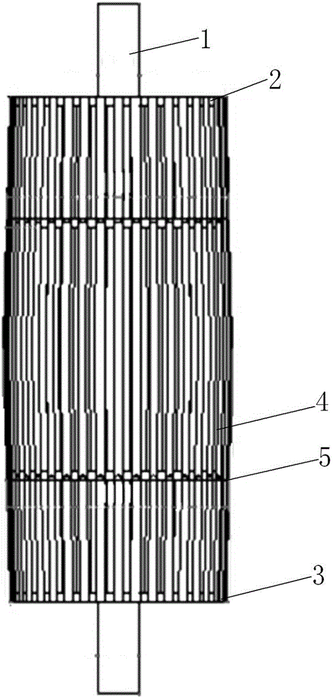
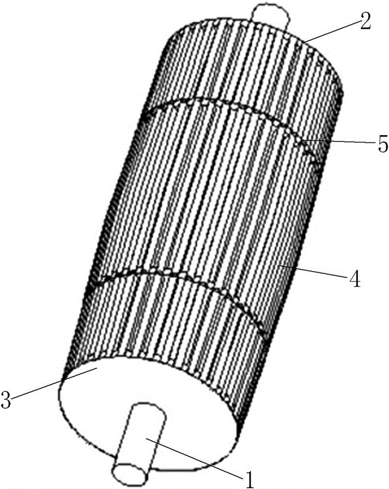
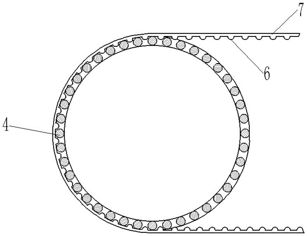
[0010] figure 1 , 2 , 3 middle: rotating shaft 1, first connecting plate 2, second connecting plate 3, connecting rod 4, hoop 5, convex body 6, conveyor belt 7.

[0011] Easy to install, low energy consumption, non-slip belt conveyor roller, the belt conveyor roller includes a rotating shaft 1, a roller assembly installed on the rotating shaft 1, and the roller assembly includes a first connecting plate 2, a second connecting plate 3, a connecting Rod 4, hoop 5, the first connecting plate 2, the second connecting plate 3 are welded and fixedly connected with the rotating shaft 1, the first connecting plate 2, the second connecting plate 3 are coaxial with the rotating shaft 1, The first connecting plate 2 and the second connecting plate 3 are circular plates, one end of the connecting rod 4 is fixedly connected with the first connecting plate...


PUM


Abstract

The invention provides a convenient-to-mount and low-energy-consumption antiskid type belt conveyor roller. The belt conveyor roller comprises a rotating shaft and a roller assembly mounted on the rotating shaft, wherein the roller assembly comprises a first connecting plate, a second connecting plate, connecting rods and hoops; the first connecting plate and the second connecting plate are fixedly connected with the rotating shaft; the first connecting plate and the second connecting plate are coaxial with the rotating shaft; the first connecting plate and the second connecting plate are round plates; and one ends of the connecting rods are fixedly connected with the first connecting plate. The belt conveyor roller has the beneficial effects that the product cannot easily skid during transmission; due to the adoption of the whole framework connection of the connecting rods, the weight of the roller product is reduced, and the roller freely rotates; the driving load of an electric motor is relatively reduced, so that consumed power is reduced; and most of the welding of the product adopts spot welding, and spot welding has the advantage of uneasy deformation over drawing welding, so that welding manufacture difficulty is reduced.

Description

technical field [0001] The invention relates to a mechanical device, in particular to a non-slip type belt conveyor roller with convenient installation and low energy consumption. Background technique [0002] Belt conveyors are used to transport various materials, and the rollers of existing belt conveyors are made of iron plates, so they are quite heavy. At the same time, the rolling processing of large iron plates and the subsequent welding production are quite cumbersome. Since drawing welding is mostly used for welding, the drawing welding of the plate is prone to severe welding deformation due to local heating, and the requirements for welding technology are relatively high. It is inconvenient to install and process, and because the self-weight of the drum is relatively large, the load driven by the motor is relatively large, thereby consuming more electric energy. In addition, when transferring more objects, the belt will slip along the surface of the drum, which wi...

Claims


Application Information

Patent Timeline
Patent Type & Authority Applications(China)
IPC IPC(8): B65G39/02
CPCB65G39/02
Inventor 苏峰
Owner NANTONG UNION MACHINERY ELECTRONTCS TECH CO LTD
Why Eureka
Try Eureka