
Long-stroke displacement restrictor

A technology of stopper and long stroke, applied in the field of long stroke stopper, can solve the problems of short life, easy damage and high maintenance cost, and achieve the effect of reducing maintenance cost, saving use cost and improving work efficiency

Active Publication Date: 2017-05-31
卢协峰
View PDF6 Cites 1 Cited by
  • Summary
  • Abstract
  • Description
  • Claims
  • Application Information

AI Technical Summary

Problems solved by technology

[0002] The stroke limiter is a safety device to protect the machine and its users, prevent the crane from crashing or restricting it to travel within a certain range. At present, the traditional limit switch type is commonly used in cranes. The principle is to rotate under force and cut off the control power supply. However, this structure is easily damaged, has a short life and high maintenance costs

Method used


Image

  • Long-stroke displacement restrictor
  • Long-stroke displacement restrictor
  • Long-stroke displacement restrictor

Examples


Embodiment

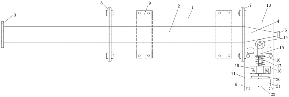
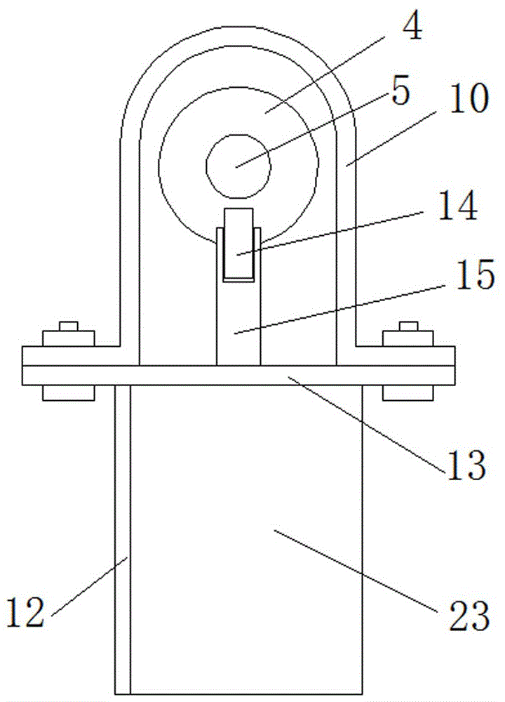
[0016] Example: such as Figure 1-3 As shown, a long stroke limiter includes a cylindrical main housing 1, a transmission rod 2 is arranged inside the main housing 1, the inner end of the transmission rod 2 protrudes from the main housing 1, and the outer end of the transmission rod 2 is provided There is a conical head 4; the outer end of the main shell 1 is docked with an outer end upper shell 10, and the outer end upper shell 10 is provided with an outer end lower shell 11 through a fixing plate; the outer end lower shell 11 is provided with There is a terminal block 18, the middle part of the terminal block 18 is provided with a vertical moving hole, two terminal posts 19 are arranged on both sides of the terminal block 18, and a terminal post contact is provided on the lower side of the terminal post; Inside the body 10, a roller 14 is set against the bottom of the conical head 4, the rolling direction of the roller 14 is consistent with the direction of the generatrix of...


PUM


Abstract

The invention discloses a long-stroke displacement restrictor. A driving rod is arranged in a cylindrical main shell; the internal end of the driving rod stretches out of the main shell; a conical head is arranged at the external end of the driving rod; an external end upper shell is arranged at the external end of the main shell in a butt joint manner; an external end lower shell is arranged below the external end upper shell through a fixing plate; a wire holder is arranged in the external end lower shell; a vertical moving hole is formed in the middle of the wire holder; two binding posts are arranged on two sides of the wire holder; binding post contacts are arranged on the lower sides of the binding posts; the conical head is positioned in the external end upper shell; an idler wheel is arranged below the conical head in a reclining manner and is arranged at the upper end of a moving rod through an idler wheel shaft; the lower end of the moving rod penetrates through the moving hole in the middle of the wire holder; a spring seat is arranged on the moving rod on the lower side of the fixing plate; a pressure spring is arranged on the moving rod between the spring seat and the wire holder; a conductive strip is fixedly arranged on the moving rod on the lower side of the wire holder; and conductive strip contacts are arranged on left and right sides of the conductive strip. The long-stroke displacement restrictor improves reliability and durability, reduces the maintenance cost, and improves the working efficiency.

Description

technical field [0001] The invention relates to a long stroke limiter. Background technique [0002] The stroke limiter is a safety device to protect the machine and its users, prevent the crane from crashing or restricting it to travel within a certain range. At present, the traditional limit switch type is commonly used in cranes. The principle is to rotate under force and cut off the control power supply. However, this structure is easily damaged, has a short service life, and has high maintenance costs. Contents of the invention [0003] The invention provides a long stroke limiter, which is more reliable and durable. [0004] In order to solve the above technical problems, the present invention adopts the following technical solutions: a long-stroke limiter, including a cylindrical main housing, a transmission rod is arranged inside the main housing, the inner end of the transmission rod protrudes from the main housing, and the transmission rod The outer end is prov...

Claims


Application Information

Patent Timeline
IPC IPC(8): B66C15/04
CPCB66C15/045
Inventor 卢协峰
Owner 卢协峰
Learn More