Gas purifying and water removing device used in CNG dispenser

A filling machine and gas cleaning technology, which is applied in the direction of gas fuel, petroleum industry, fuel, etc., can solve the problems of affecting gas filling efficiency, increasing the space volume of pipeline filters, and high after-sales repair costs, so as to ensure heat exchange effect, Improve heat exchange efficiency, facilitate installation and maintenance

Inactive Publication Date: 2017-05-31
TOKHEIM HENGSHAN TECH GUANGZHOU
View PDF0 Cites 0 Cited by
  • Summary
  • Abstract
  • Description
  • Claims
  • Application Information

AI Technical Summary

Problems solved by technology

The disadvantages of the prior art are as follows: 1. The filter element is a very vulnerable part (the replacement cycle of a new gas station is within one week), and the cost of a high-precision filter element is much higher than that of the filter element currently in use. Frequent replacement of high-precision The filter element is very expensive for the after-sales repair cost; 2. The gas flow rate affects the gas filling efficiency, and it is also a key point that customers value most for product quality. In order not to affect the flow rate when the gas passes through the high-precision filter element, it is necessary to increase the filtration. area, greatly increasing the space volume occupied by the pipeline filter

Method used


Image

  • Gas purifying and water removing device used in CNG dispenser
  • Gas purifying and water removing device used in CNG dispenser
  • Gas purifying and water removing device used in CNG dispenser

Examples


Embodiment Construction

[0018] For the convenience of those skilled in the art to understand, the present invention will be further described in detail below in conjunction with the accompanying drawings and embodiments.

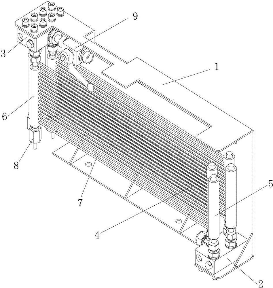
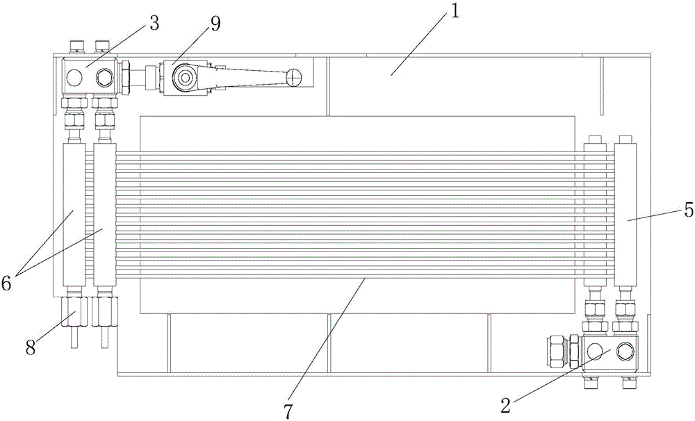
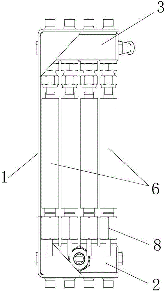
[0019] Such as Figure 1 to Figure 3 As shown, the air purification and dehydration device used for CNG filling machines includes an outer frame 1, an air inlet valve 2, an air outlet valve 3 and a plurality of condensed air purification components 4, the air inlet valve 2 and the outlet valve The gas port valves 3 are all installed on the outer frame 1; the condensed air purification assembly 4 includes an air inlet pipe 5, an air outlet pipe 6 and a plurality of heat dissipation capillary tubes 7, the lower end of the air inlet pipe 5 is connected with the air inlet valve 2, and the outlet The upper end of the trachea 6 is connected with the air outlet valve 3, and the plurality of heat dissipation capillary tubes 7 are arranged in a row from top to bottom, and one end of the plu...


PUM


Abstract

The invention discloses a gas purifying and water removing device used in a CNG dispenser. The gas purifying and water removing device comprises an outer frame, a gas inlet valve, a gas outlet valve and multiple condensating gas purifying assemblies, wherein the gas inlet valve and the gas outlet valve are installed on the outer frame; each condensating gas purifying assembly comprises a gas inlet pipe, a gas outlet pipe and multiple heat dissipating capillary tubes, wherein the lower end of the gas inlet pipe is connected with the gas inlet valve, the upper end of the gas outlet pipe is connected with the gas outlet valve, the heat dissipating capillary tubes are arrayed from top to bottom in a row, one end of each heat dissipating capillary tube is connected with the corresponding gas inlet pipe, and the other end of each heat dissipating capillary tube is connected with the corresponding gas outlet pipe; a blow-down valve is arranged at the lower end of each gas outlet pipe, and the upper end of each gas inlet pipe is closed. The condensating gas purifying assemblies do not need to be replaced frequently and are convenient to maintain; the condensating gas purifying assemblies formed by the gas inlet pipes, the gas outlet pipes and the multiple heat dissipating capillary tubes are low in manufacturing cost and high in working efficiency.

Description

technical field [0001] The invention relates to a water and gas purifying device, in particular to a gas purifying and water purifying device for a CNG filling machine. Background technique [0002] The existing high-pressure natural gas pipeline water removal device uses a sintered or membrane filter element filter, and the requirement for effective filtration of water molecules is very high, and the filter element accuracy must reach 1 μm. The disadvantages of the prior art are as follows: 1. The filter element is a very vulnerable part (the replacement cycle of a new gas station is within one week), and the cost of a high-precision filter element is much higher than that of the filter element currently in use. Frequent replacement of high-precision The filter element is very expensive for the after-sales repair cost; 2. The gas flow rate affects the gas filling efficiency, and it is also a key point that customers value most for product quality. In order not to affect the...

Claims


Application Information

Patent Timeline
IPC IPC(8): C10L3/10
CPCC10L3/106C10L2290/06
Inventor 伍卫卫
Owner TOKHEIM HENGSHAN TECH GUANGZHOU
Why Eureka
Try Eureka