
A new hanger rod device

A coat hanger rod and a new type of technology, which are applied in washing devices, other drying devices, textiles and paper making, etc., can solve the problems of secondary pollution, unadjustable support rods, unsuitable for popularization and use, etc., so as to reduce labor and improve operation. The effect of simplicity

Active Publication Date: 2017-12-22
HAIMEN MAOFA ART DESIGN CO LTD
View PDF3 Cites 0 Cited by
  • Summary
  • Abstract
  • Description
  • Claims
  • Application Information

AI Technical Summary

Problems solved by technology

[0002] Clothes hanger rods are very common in our daily life. Traditional clothes hanger rods are generally supported by support rods. Since the support rods are not adjustable, the support height is limited. If it is not enough, it will be dragged to the ground to cause secondary pollution, and it needs to be cleaned repeatedly. At the same time, there are also some hanger rods fixed on the top of the wall, but they need to use the hanger fork when collecting and drying clothes. The operation is extremely cumbersome and inconvenient. Height-adjustable clothes hanger rod device, but its price is expensive, and the cost of use is relatively large, so it is not suitable for popularization and use

Method used


Image

  • A new hanger rod device
  • A new hanger rod device
  • A new hanger rod device

Examples


Embodiment Construction

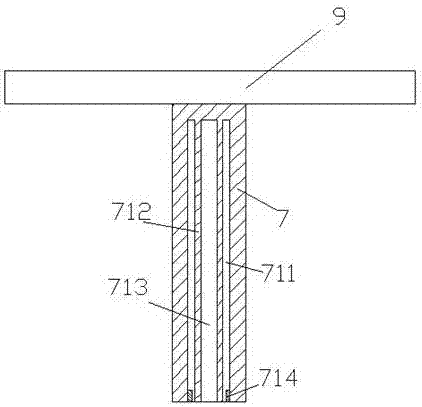
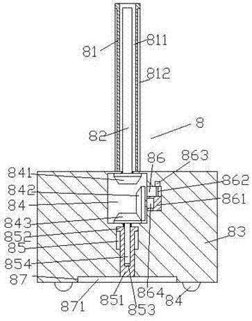
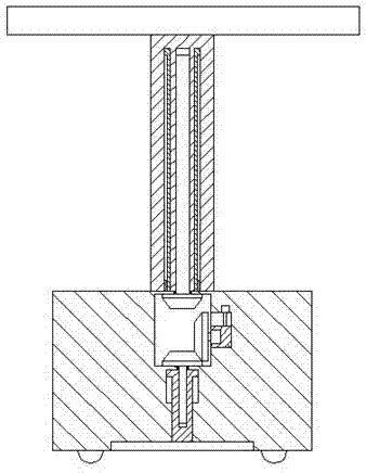
[0020] like Figure 1-Figure 6 As shown, a novel clothes hanger rod device of the present invention includes a rack rod 7, a support portion 8 and a drying rack 9 fixedly arranged on the top of the rack rod 7, and the first housing extending downwards is arranged inside the rack rod 7. Cavity 711, the top and middle end of the first receiving cavity 711 is provided with a first socket pipe 712 extending downward, and a first internal thread cavity 713 is provided in the first socket pipe 712, and the support part 8 is composed of a second socket pipe 81 extending upward and penetrating into the first receiving chamber 711 and a stand 83 arranged at the bottom of the second socket pipe 81, and the left and right outer walls of the second socket pipe 81 correspond to A first sliding groove 812 is provided, and a second receiving chamber 811 is provided in the second sleeve pipe 81 for sliding fit connection with the first sleeve pipe 712 , and the bottom of the inner wall on bot...


PUM


Abstract

The invention discloses a novel laundry rack rod device. The device comprises a rack rod, a supporting part and an airing rack fixedly arranged on the top of the rack rod. The rack rod is internally provided with a first containing cavity extending downward, a first socketed pipe extending downward is arranged at the middle of the top in the first containing cavity, a first internal thread cavity is formed in the first socketed pipe, the supporting part comprises a second socketed pipe and a rack base, the second socketed pipe extends upwards and penetrates through the first containing cavity, the rack base is arranged at the bottom of the second socketed pipe, the outer walls of the left and right sides of the second socketed pipe are correspondingly provided with first sliding grooves, and the second socketed pipe is internally provided with a second containing cavity matched and connected with the first socketed pipe in a sliding mode; the bottoms of the inner walls of the two sides of the first containing cavity are correspondingly provided with guide movable blocks, and the guide movable blocks penetrate through the first sliding grooves and are matched and connected with the first sliding grooves in a sliding mode. The device is simple in structure and convenient to operate, can be automatically controlled to ascend and descend, and is stable in support, low in cost and suitable for application and popularization.

Description

technical field [0001] The invention relates to the technical field of daily necessities, in particular to a novel clothes hanger rod device. Background technique [0002] Clothes hanger rods are very common in our daily life. Traditional clothes hanger rods are generally supported by support rods. Since the support rods are not adjustable, the support height is limited. If it is not enough, it will be dragged to the ground to cause secondary pollution, and it needs to be cleaned repeatedly. At the same time, there are also some hanger rods fixed on the top of the wall, but they need to use the hanger fork when collecting and drying clothes. The operation is extremely cumbersome and inconvenient. The height-adjustable clothes hanger rod device is expensive, and the use cost is relatively large, so it is not suitable for popularization. Contents of the invention [0003] The technical problem to be solved by the present invention is to provide a novel clothes hanger rod de...

Claims


Application Information

Patent Timeline
Patent Type & Authority Patents(China)
IPC IPC(8): D06F57/02
CPCD06F57/02
Inventor 李全平
Owner HAIMEN MAOFA ART DESIGN CO LTD
Learn More