
Constraint damping noise reduction plate

A technology of restraint damping and restraint plate, applied in the field of vibration reduction and noise reduction, can solve problems such as weakening the effect of vibration reduction and noise reduction, achieve excellent vibration reduction and noise reduction effect, ensure the geometric size, and improve the vibration reduction ability.

Active Publication Date: 2017-05-31
QINGDAO CREATE ENVIRONMENT CONTROL TECH +2
View PDF10 Cites 10 Cited by
  • Summary
  • Abstract
  • Description
  • Claims
  • Application Information

AI Technical Summary

Problems solved by technology

However, after a lot of engineering practice, it is found that during work, part of the vibration of the rail will be directly transmitted to the restraint plate through the rigid buckle structure and then radiate noise to the outside, thus weakening the actual vibration and noise reduction effect of the product
In addition, the same problem exists when such constrained damping structures are used in applications such as ship decks and power equipment shells for vibration and noise reduction

Method used


Image

  • Constraint damping noise reduction plate
  • Constraint damping noise reduction plate
  • Constraint damping noise reduction plate

Examples


Embodiment 1

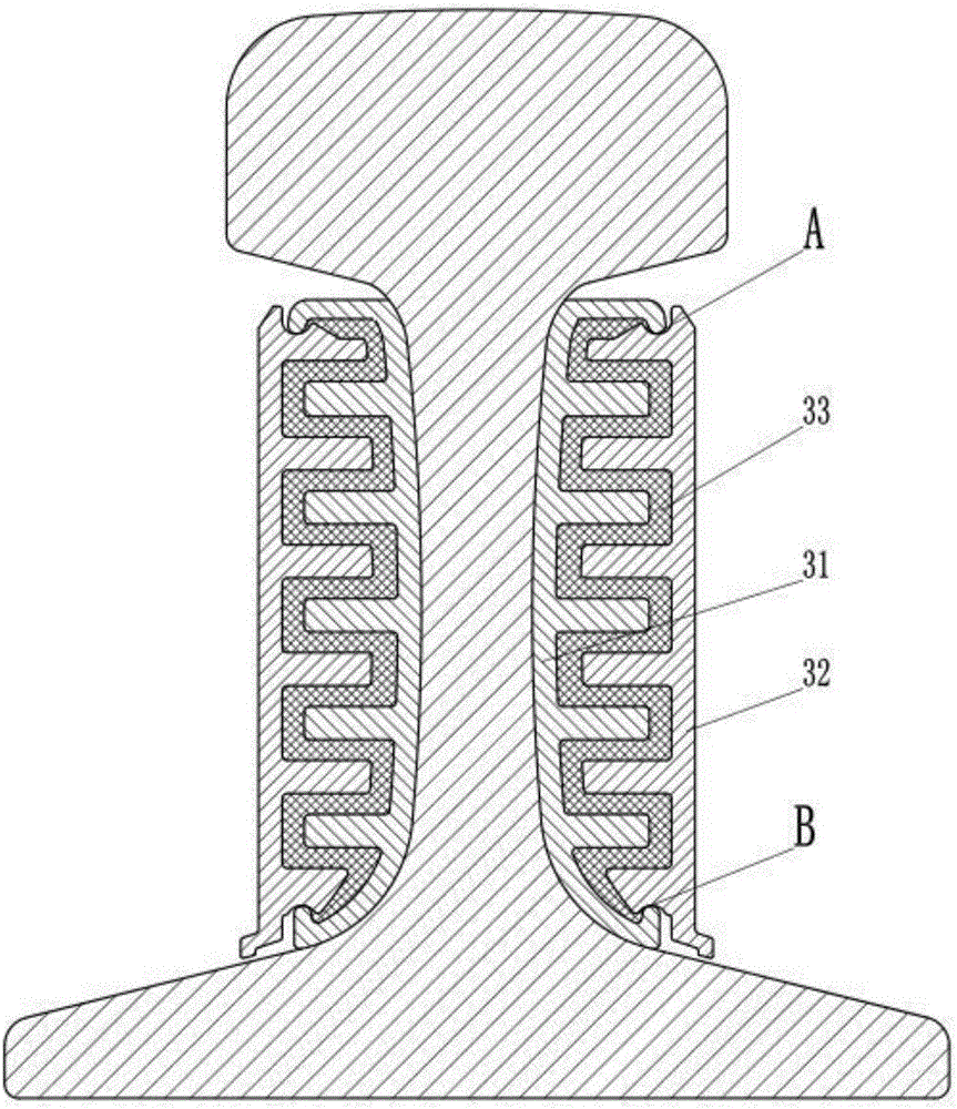
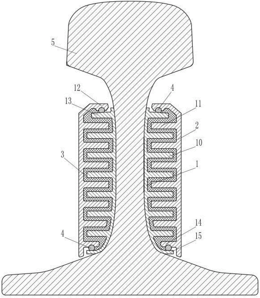
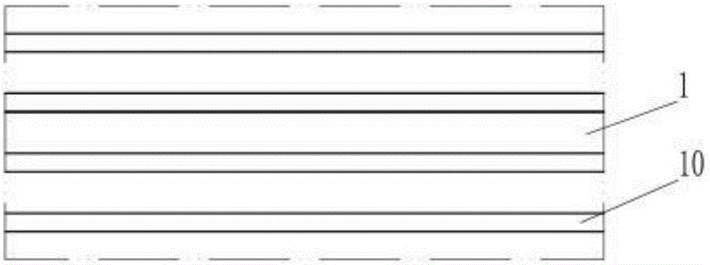
[0021] Such as figure 2 and image 3 The constrained damping and noise reduction plate of the present invention shown in the present invention includes a connecting plate 1 and a constraining plate 2. The connecting plate 1 and the constraining plate 2 are respectively provided with convex-concave structures. The convex-concave structures are specifically continuous ribs 10 and The continuous ribs 11 arranged at intervals on the constraining plate 2, the convex and concave structures on the connecting plate 1 and the constraining plate 2 are staggered to form a damping chamber, and the damping material is arranged in the damping chamber to form a damping layer 3. Correspondingly, the splicing of the connecting plate and the splicing of the constraining plate are respectively set at the splicing places, including the splicing of the connecting plate 13 and 15 set on both sides of the connecting plate 1, and correspondingly, the splicing of the constraining plate 2 is set on bo...

Embodiment 2

[0028] Such as Figure 5 The difference between the constrained damping and noise-reducing plate of the present invention shown in Embodiment 1 is that, except between the combined ribs 13 of the connecting plate and the combined ribs 12 of the restraining plate and between the combined ribs 15 of the connecting plate and the combined ribs 14 of the constraining plate In addition to the elastic spacer strips 4 respectively arranged between the connecting plate and the restraining plate, there is also an elastic spacer strip 6 to keep the connecting plate and the restraining plate elastically isolated in the direction of the convex embossing of the constraining plate. The elastic spacer strip 6 is set Between the front ends of the corrugations 18 and 19 on the constraining plate 2 and the connection plate 1; in addition, the constraining plate spliced ​​corrugations 12 and 14 at the joint of the constricting plate 1 and the constraining plate 2 are respectively located at the sp...

Embodiment 3

[0033] Such as Figure 6 The difference between the constrained damping and noise-reducing plate of the present invention as shown in Embodiment 1 is that the conjoined corrugations 13 and 15 of the connecting plate 1 and constraining plate 2 are respectively located on the outer sides of the constraining plate compositing protruding corrugations 12 and 14. The joint ribs 13 and 15 of the connecting plate and the joint ribs 12 and 14 of the restraining plate are provided with corresponding positioning grooves on the sides of each other. In addition, a counterweight installation interface is provided on the outside of the restraint plate 2, and the counterweight installation interface is specifically the installation groove provided on the restraint plate 2, and the installation groove is provided by the restraint plate 2. The draw-in groove wall 8 surrounds, and counterweight 7 is arranged in the installation groove, and wherein counterweight 7 is made of steel plate.

[0034...


PUM


Abstract

The invention belongs to the field of vibration and noise reduction, and particularly relates to a constraint damping device capable of increasing the structure damping and achieving a good vibration and noise reduction function. A constraint damping noise reduction plate comprises a connecting plate and a constraint plate, wherein a connecting plate splicing rib and a constraint plate splicing rib are correspondingly arranged at spliced parts of the connecting plate and the constraint plate respectively; at least one of the connecting plate splicing rib and the constraint plate splicing rib is provided with a positioning groove in the mutually matched side face; an elastic isolating strip made of an elastic material is also arranged between the connecting plate splicing rib and the constraint plate splicing rib; the elastic isolating strip is partially embedded into the positioning groove; the connecting plate and the constraint plate are connected through an elastic isolating strip splicing buckle; the elastic isolating strip and a damping layer keep the connecting plate and the constraint plate elastically isolated. The constraint damping noise reduction plate is simple in structure and convenient to use, and can better block own vibration transfer, so as to achieve a better vibration and noise reduction effect.

Description

technical field [0001] The invention belongs to the field of vibration reduction and noise reduction, and specifically relates to a constraint damping device that can increase the damping of the structure itself and realize good vibration reduction and noise reduction functions. Background technique [0002] With the rapid development of economic construction and transportation infrastructure construction, rail transportation methods such as subway, elevated light rail, ordinary railway and high-speed railway are playing an increasingly important role in the field of freight and passenger transportation because of their advantages of large carrying capacity, convenience, safety and reliability. role. How to reduce the noise pollution during rail transportation, reduce the vibration and wear of rails during transportation, thereby prolonging the life of the rail and improving the safety and comfort of rail transportation has become a difficult problem closely related to the p...

Claims


Application Information

Patent Timeline
Patent Type & Authority Applications(China)
IPC IPC(8): E01B19/00
CPCE01B19/00E01B19/003
Inventor 尹学军刘兴龙孔祥斐王乾安李维赞薛松陈常福刘永强马学强
Owner QINGDAO CREATE ENVIRONMENT CONTROL TECH
Learn More