Vibration isolation system with back pressing devices

A vibration isolation system and vibration isolator technology, applied in vibration suppression adjustment, non-rotation vibration suppression, spring/shock absorber, etc. problems, to achieve stable and reliable natural frequency and vibration isolation effect, small variation range of natural frequency, and ensure the effect of vibration isolation system

Active Publication Date: 2017-03-22
QINGDAO CREATE ENVIRONMENT CONTROL TECH +1
View PDF7 Cites 9 Cited by
  • Summary
  • Abstract
  • Description
  • Claims
  • Application Information

AI Technical Summary

Problems solved by technology

[0004] After several years of practice and exploration in many large-scale projects, the law has been discovered: the actual natural frequency of the vibration isolation system is often lower than the theoretical design, and even if the stiffness of the springs is measured one by one and carefully selected to combine the theory required for calculation analysis and design values ​​of stiffness, are unavoidable
[0005] After repeated research and tests, the reason was finally found: multiple steel spring vibration isolators are often used in this type of vibration isolation system at the same time, and each steel spring vibration isolator may contain multiple steel spring elements. Under the cumulative effect of errors and assembly errors, the static load provided by the weight of the equipment is often unable to allow all or most of the steel spring elements to enter the stage of linear change in which the external force they bear is proportional to their own compression displacement, even when the equipment is running. After that, especially when the natural frequency of the vibration isolation system is high (for example, above 10 Hz), the vibration amplitude of the mass block is small, and it is still possible that a considerable part of the steel spring elements are completely or partially in the working stage of nonlinear changes, resulting in the overall vibration of the vibration isolation system. The stiffness is lower than the theoretical value, and the natural frequency is lower, so under the same disturbance, the vibration speed and amplitude are too large, resulting in the vibration value exceeding the standard
[0006] In addition, for some mechanical equipment with harsh application environments, such as ship power equipment, due to the violent shaking of the hull when the wind and waves are strong, the power equipment will inevitably shake. Therefore, the vibration isolation system of the power equipment must not only bear pressure loads, but also It must be able to withstand a certain pull-up load to ensure the safety of the power equipment and the stability of the vibration isolation system, otherwise the power equipment or the vibration isolation device in the vibration isolation system will be in danger of overturning
Similarly, the short prefabricated slab floating track bed also has such problems. When the rail vehicle enters from one end, due to the short prefabricated slab’s light weight, it will produce a seesaw effect, that is, the other end of the short prefabricated slab has an upward warp. If the trend cannot be effectively controlled, the vibration isolator on the tilted side of the short prefabricated slab will have insufficient pressure, which will easily lead to problems such as the displacement of the short prefabricated slab or the overturning of the elastic components in the vibration isolator, which will bring serious problems to daily operations. Security risks
In order to ensure safety, the traditional method is to use rigid limit, which inevitably forms a vibration short circuit, which greatly reduces the vibration and noise reduction effect of the vibration isolation system

Method used


Image

  • Vibration isolation system with back pressing devices
  • Vibration isolation system with back pressing devices
  • Vibration isolation system with back pressing devices

Examples


Embodiment 1

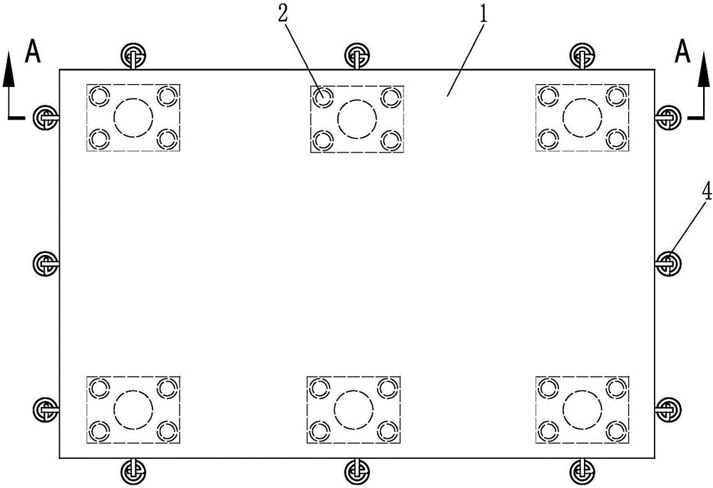
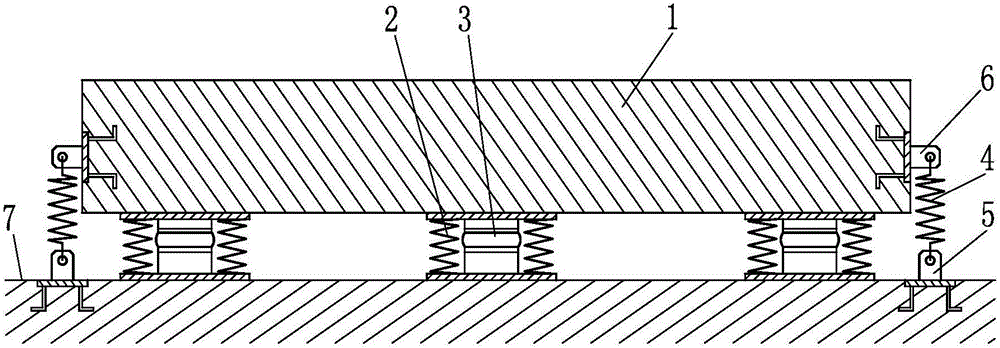
[0028] Such as figure 1 , figure 2 The shown vibration isolation system of the present invention with a back pressure device includes a counterweight stand 1 and a vibration isolator, the counterweight stand 1 is a platen made of reinforced concrete, and the vibration isolator is elastic The spring-damping vibration isolator composed of the supporting element 2 and the damping device 3, wherein the elastic supporting element 2 includes four helical steel springs, the damping device 3 is specifically a viscous damping device, and the vibration isolator is located between the base 7 and the counterweight platform 1, the counterweight platform 1 is supported on the vibration isolator; in addition, it also includes a back pressure device, the back pressure device includes a back pressure elastic element 4 and a connecting piece 5, wherein the back pressure elastic element 4 is a metal tension spring , the connecting piece 5 is an ear plate with a hooking hole, the connecting pie...

Embodiment 2

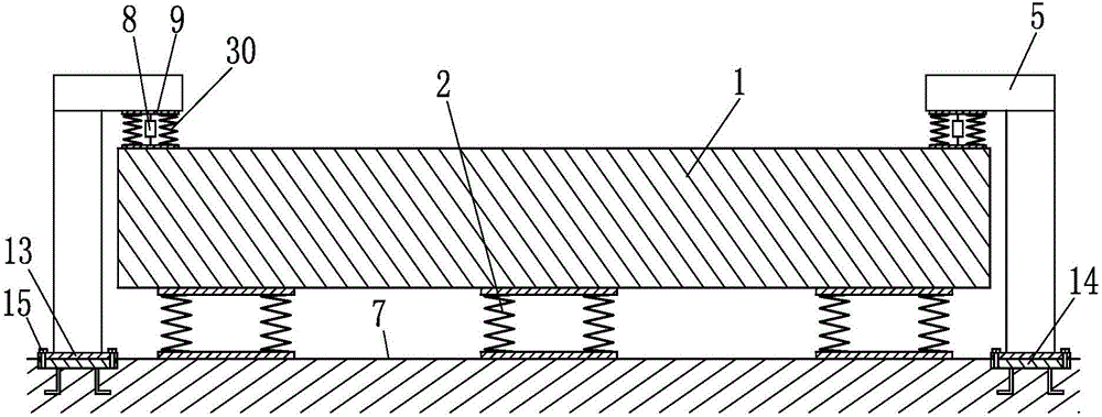
[0033] Such as image 3 The difference between the vibration isolation system with the back pressure device of the present invention and the first embodiment is that the vibration isolator is only a spring vibration isolation device composed of elastic support elements 2, and the elastic support elements 2 are specifically four spiral steel Spring; In addition, in the back pressure device of this example, connector 5 is the detaining connector with connecting flange 13, and this detaining connecting part is welded by channel steel, utilizes fastener 15 to connect flange 13 and base The metal anchors 14 pre-buried in 7 are fixed together to realize the fixing of the connecting piece 5 on the base 7; in addition, the back pressure elastic element is composed of a pressure equalizing plate 9, two compression springs 30 and a damping device 8, in which The pressing plate is made of steel plate, the compression spring 30 is a helical steel spring, and the damping device 8 is specif...

Embodiment 3

[0036] Such as Figure 4 The vibration isolation system with back pressure device of the present invention shown in the present invention differs from Embodiment 2 in that bosses 31 are provided on both sides of counterweight platform 1; The spring damping and vibration isolation device composed of the damping device 3, the elastic support element 2 is specifically a helical steel spring, and the damping device 3 is specifically a viscous damping device; in the back pressure device, the connecting piece 5 is made of I-beam, and the connecting piece 5 The lower end of the lower end is fixed on the base 7, and the anti-pressure elastic element 4 is a compression spring composed of a helical steel spring. One end of the back pressure elastic element 4 acts on the connecting piece 5 , and the other end of the back pressure acts on the boss 31 in the counterweight platform 1 . In order to prevent the anti-pressure elastic element 4 from accidentally moving during use, the connecti...


PUM


Abstract

The invention relates to a vibration isolation system with back pressing devices, and belongs to the technical field of vibration reduction of civil engineering structures. The vibration isolation system is used for controlling influences of vibration of machinery equipment on external environments or relieving influences of vibration of the external environments on the machinery equipment. The vibration isolation system comprises a counterweight bench and vibration isolators, the vibration isolators are located between a base and the counterweight bench which is supported on the vibration isolators, elastic supporting elements are arranged in the vibration isolators, and the elastic supporting elements are at least composed of metal helical springs; and the vibration isolation system further comprises the back pressing devices, each back pressing device comprises a back pressing elastic element and a connecting part, one end of each back pressing elastic element acts on the counterweight bench, the other end of each back pressing elastic element acts on the corresponding connecting part, the connecting parts is connected with the base or vibration isolator bases, and the direction of acting force of the back pressing elastic elements on the counterweight bench is opposite to that of supporting force of the elastic supporting elements on the counterweight bench. Compared with the prior art, according to the vibration isolation system with the back pressing devices, the inherent frequency is easy to control, and the vibration isolation effect is better guaranteed.

Description

technical field [0001] The invention belongs to the technical field of vibration reduction of civil engineering structures, and in particular relates to a vibration isolation system for controlling the impact of the vibration of machine equipment on the external environment or reducing the impact of the vibration of the external environment on the machine equipment. Background technique [0002] In recent years, with the continuous advancement of my country's industrial upgrading, various large-scale rotary equipment are widely used in industrial production and urban construction, such as various generator sets, water pumps, fans, compressors, etc. The problem of vibration and noise control has also been paid more and more attention. Taking the mechanical cooling fan system of an urban gas-fired power plant as an example, the excitation frequency of its motor, gearbox, and blades is very rich. The vibration attenuation in the building structure is small, and it is easy to exc...

Claims


Application Information

Patent Timeline
IPC IPC(8): F16F15/04
CPCF16F15/046
Inventor 尹学军孔祥斐王乾安付学智薛松刘兴龙刘永强
Owner QINGDAO CREATE ENVIRONMENT CONTROL TECH
Why Eureka
Try Eureka