track floating track bed
A technology for floating ballast bed and track, applied in the field of ballast bed, can solve the problems such as the inability to guarantee the most reasonable level of the vibration isolation system, the nonlinear change of the steel spring element, and the overturning of the elastic element in the vibration isolator, so as to achieve a reasonable and controllable change in the natural frequency , low vibration and noise levels, high vibration isolation efficiency
- Summary
- Abstract
- Description
- Claims
- Application Information
AI Technical Summary
Problems solved by technology
Method used
Image
Examples
Embodiment 1
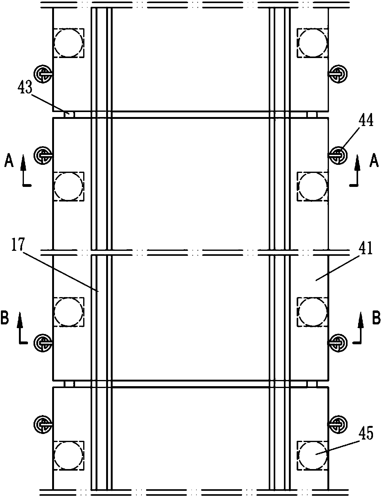
[0029] like figure 1 The track floating track bed of the present invention is shown, including a floating plate 41 and an elastic supporting element 45, the floating plate 41 is a side-mounted floating plate, and the adjacent floating plates 41 are connected by a shearing force transmission device 43, so The shearing force transmission device 43 is specifically a central shearing hinge, such as figure 2 and image 3 As shown, the elastic support element 45 includes a spring damping vibration isolation device 42 composed of a coil steel spring and a damping device, and a height-adjusting washer 19, wherein the damping device is specifically a viscous damping device, and the spring damping vibration isolation device 42 is located on the base 7 and the floating plate 41, the floating plate 41 is supported on the spring damping vibration isolation device 42 through the height-adjusting gasket 19; in addition, it also includes a back pressure device 44, which includes a plurality...
Embodiment 2
[0034] like Figure 4 and Figure 5 The difference between the floating track bed of the present invention and the first embodiment is that the floating plate 41 is provided with a partial boss 31, and the boss 31 is also provided with an installation channel 12, and between adjacent floating plates 41 Connect with the shear force transfer device 43, the shear force transfer device 43 is specifically an upper-mounted shear hinge; in addition, in this example, the elastic support element is composed of a spring damping vibration isolation device 42, a height-adjusting spacer 19 and a plate end vibration isolation device 46 Composition, wherein, the spring damping vibration isolation device 42 is placed in the housing 16, the housing 16 is preset and fixed in the body of the floating plate 41, and the inside of the housing 16 is also fixedly equipped with a bearing member 18, and the middle part of the bearing member A central through hole is left, and the size of the central t...
Embodiment 3
[0037] like Image 6 and Figure 7 The difference between the floating track bed of the present invention and the second embodiment is that the body of the floating plate 41 is provided with an installation channel 12; in the back pressure device 44, one end of the connecting piece 5 is fixed on the base 7 through an anchoring structure The back pressure elastic element 4 is a compression spring made of rubber spring, and the two ends of the rubber spring are also vulcanized and fixed with a pressure equalizing plate 9, and the screw of the connecting piece 5 is arranged in the installation channel 12, which runs through the floating plate 41 And the back pressure elastic element 4, utilize the locking nut 11 that screw rod top is provided with, make the back pressure elastic element 4 back pressure act on the top surface of the floating plate 41, and the force direction of the compression spring to the floating plate is consistent with the elastic support The supporting forc...
PUM
 Abstract
Description
Claims
Application Information
 - R&D
- Intellectual Property
- Life Sciences
- Materials
- Tech Scout
- Unparalleled Data Quality
- Higher Quality Content
- 60% Fewer Hallucinations
Browse by: Latest US Patents, China's latest patents, Technical Efficacy Thesaurus, Application Domain, Technology Topic, Popular Technical Reports.
© 2025 PatSnap. All rights reserved.Legal|Privacy policy|Modern Slavery Act Transparency Statement|Sitemap|About US| Contact US: help@patsnap.com


