Tensile vibration isolation device

A vibration isolation and tensile technology, applied in the field of vibration isolation devices and vibration isolation devices, can solve the problems of seesaw effect, endanger the safety of ship power equipment, failure of vibration isolation system, etc., and achieve broad market application prospects, vibration isolation Stable and reliable performance, high vibration isolation efficiency

Active Publication Date: 2018-01-02
QINGDAO CREATE ENVIRONMENT CONTROL TECH +1
View PDF7 Cites 0 Cited by
  • Summary
  • Abstract
  • Description
  • Claims
  • Application Information

AI Technical Summary

Problems solved by technology

Taking large-scale forging equipment as an example, when working, the forging working part will lift up immediately after impacting the workpiece. At this time, the impact on the workbench will be transmitted to the steel spring vibration isolator under the equipment. It does not act continuously on the workbench, so the steel spring vibration isolator will rebound immediately after being compressed and deformed, and because the existing steel spring vibration isolators generally cannot bear the upward pulling force, the steel spring vibration isolator may be caused by insufficient pressure. If the displacement is serious, the spring parts in the steel spring vibration isolator will jump when they rebound to exceed their free height. When the impact is very strong, the jumping range of the spring parts may be too large. In the case of falling out and dumping, this situation will cause the steel spring vibration isolator to lose part or even all of its elastic support capacity, affecting the normal use and operation safety of the equipment
[0004] Similarly, the short prefabricated slab floating track bed also has such problems. When the rail vehicle enters from one end, due to the short prefabricated slab's light weight, a seesaw effect will occur, that is, the other end of the short prefabricated slab has an upward warp. If the trend cannot be effectively controlled, the steel spring vibration isolator on the tilted side of the short prefabricated slab will have insufficient pressure, which will easily cause the short prefabricated slab to shift or the elastic elements in the steel spring vibration isolator to jump out or overturn, etc. problems, bringing safety hazards to daily operations
[0005] In addition, the steel spring vibration isolation devices of ship power equipment also have such problems. When encountering strong sea waves, the ship will shake violently, and the ship power equipment will inevitably shake together. In severe cases, some steel spring vibration isolation devices The borne load may be completely released, and the spring parts may jump out or fall easily, causing the vibration isolation system to fail and even endangering the safety of the ship's power equipment

Method used


Image

  • Tensile vibration isolation device
  • Tensile vibration isolation device
  • Tensile vibration isolation device

Examples


Embodiment 1

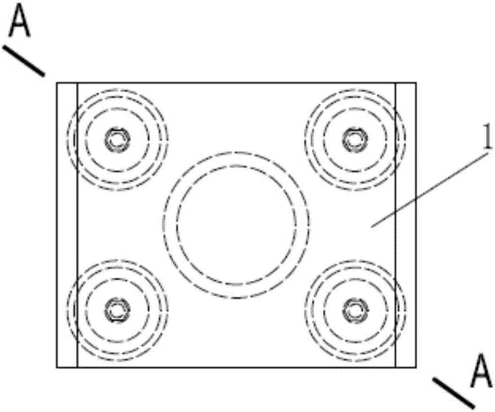
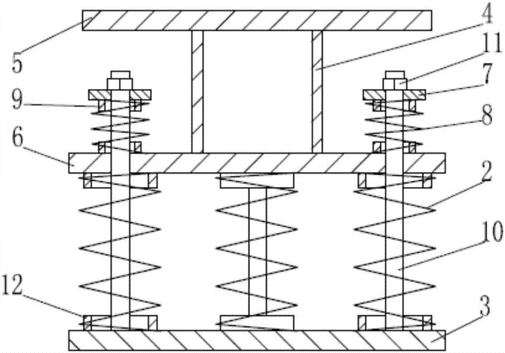
[0026] Such as figure 1 , figure 2 The tensile and vibration isolation device of the present invention shown includes a base plate 3 and an elastic support element 2. The elastic support element is a metal compression spring composed of spiral steel springs. There are four spiral steel springs. In addition, it also includes a back pressure The elastic element 8, the back pressure plate 7 and the connecting piece 1. The back pressure elastic element 8 is specifically a spiral steel spring. The back pressure elastic element 8 and the elastic supporting element 2 are arranged in one-to-one correspondence. The connecting piece 1 consists of a connecting tube 4, The middle bearing plate 6 and the outer connecting plate 5 are welded and combined, the base plate 3 is provided with a connecting rod 10, and the bottom end of the connecting rod 10 is welded and fixedly connected to the base plate 3, and the counter pressure plate 7 and its limiting member 11 are arranged on the connecting...

Embodiment 2

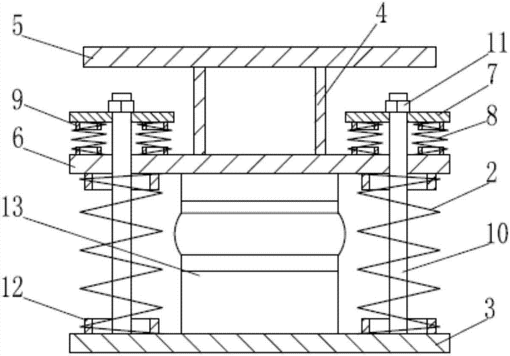
[0031] Such as image 3 The difference between the tensile and vibration isolation device of the present invention shown in the first embodiment is that each group of counter-pressure elastic elements 8 matched with the counter-pressure plate 7 includes two compression springs, and the compression springs are specifically coil steel springs. In addition, the connecting rod 10 passes through the gap surrounded by the plurality of compression springs and is connected to the counter pressure plate 7, and the two compression springs are arranged symmetrically and evenly around the connecting rod 10. In addition, in order to improve the vibration damping and energy consumption capacity of the tensile vibration isolation device of the present invention, a damping device is also provided between the middle bearing plate 6 and the base plate 3, and the damping device is specifically a viscous damping device 13.

[0032] Compared with the first embodiment, in the technical solution describ...

Embodiment 3

[0035] Such as Figure 4 with Figure 5 The difference between the tensile and vibration isolation device of the present invention shown in the first embodiment is that the counter-pressure plate 7 is an integral rectangular plate, and a central through hole is provided in the middle of the plate body to make way for the connecting pipe 4. In addition, a damping device is provided between the counter pressure plate 7 and the middle bearing plate 6, and the damping device is specifically four hydraulic damping devices 14.

[0036] Compared with the second embodiment, in the technical solution described in this example, the damping device is arranged between the counter pressure plate 7 and the middle bearing plate 6, which can leave more space for placing the elastic support element 2 to fully satisfy the heavy load. Under the conditions, the use of a larger number of elastic support elements is required; in addition, due to the damping device provided between the back pressure pla...


PUM


Abstract

The invention belongs to the field of vibration control, and in particular, relates to a tensile vibration isolation device. The tensile vibration isolation device comprises a substrate and an elastic support element; and the elastic support element includes a metal compression spring. The tensile vibration isolation device further comprises a reverse pressing elastic element, a reverse pressing plate and a connecting piece; a middle force bearing plate and an outer connecting plate are arranged in the connecting piece; a connecting rod or a shell is arranged on the substrate; the bottom end of the connecting rod or the shell is fixedly connected with the substrate; the reverse pressing plate and a limiting piece thereof are arranged at the top of the connecting rod, or the reverse pressing plate is fixed at the top of the shell; the reverse pressing elastic element is positioned between the reverse pressing plate and the middle force bearing plate; and the support elastic element is positioned between the middle force bearing plate and the substrate. The tensile vibration isolation device is simple in structure, can bear both downward pressure and upward tensile force, is high in vibration isolation efficiency, is stable and reliable in performance, can be widely applied to elastic vibration isolation foundation engineering in various ship power, industrial rotating equipment or rail transit vehicle operations, and is broad in market prospect.

Description

Technical field [0001] The invention belongs to the field of vibration control, and specifically relates to a vibration isolation device, in particular to a vibration isolation device that can be widely used for vibration isolation of track floating slab track beds, equipment or equipment foundations. Background technique [0002] In recent years, with the continuous advancement of my country’s industrial upgrading, various large-scale impact or rotary equipment is widely used in industrial production and commercial fields, such as various forging equipment, stamping equipment, nuclear power turbine generator sets, etc., at the same time, these The management of vibration and noise generated by equipment during operation has also attracted increasing attention. At present, in order to control such vibration and noise problems, the principle of vibration isolation is mostly adopted. Mass and elastic elements are used to form a vibration isolation system. The equipment is placed on ...

Claims


Application Information

Patent Timeline
Patent Type & Authority Patents(China)
IPC IPC(8): F16F15/02F16F15/06F16F15/08
CPCF16F15/02F16F15/022F16F15/06F16F15/085
Inventor 尹学军徐建孔祥斐王乾安付学智薛松刘兴龙刘永强陈常福
Owner QINGDAO CREATE ENVIRONMENT CONTROL TECH
Why Eureka
Try Eureka