Tensile Elastic Vibration Isolator
A vibration isolator and elastic technology, applied in the field of vibration control, can solve the problems of insufficient pressure of the steel spring vibration isolator, generation of seesaw effect, failure of vibration isolation system, etc. Stable and reliable, stable and reliable working condition
- Summary
- Abstract
- Description
- Claims
- Application Information
AI Technical Summary
Problems solved by technology
Method used
Image
Examples
Embodiment 1
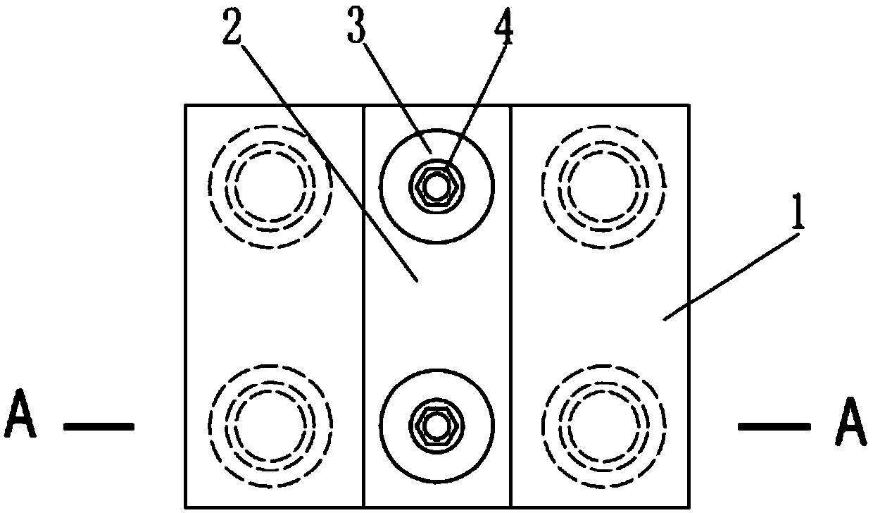
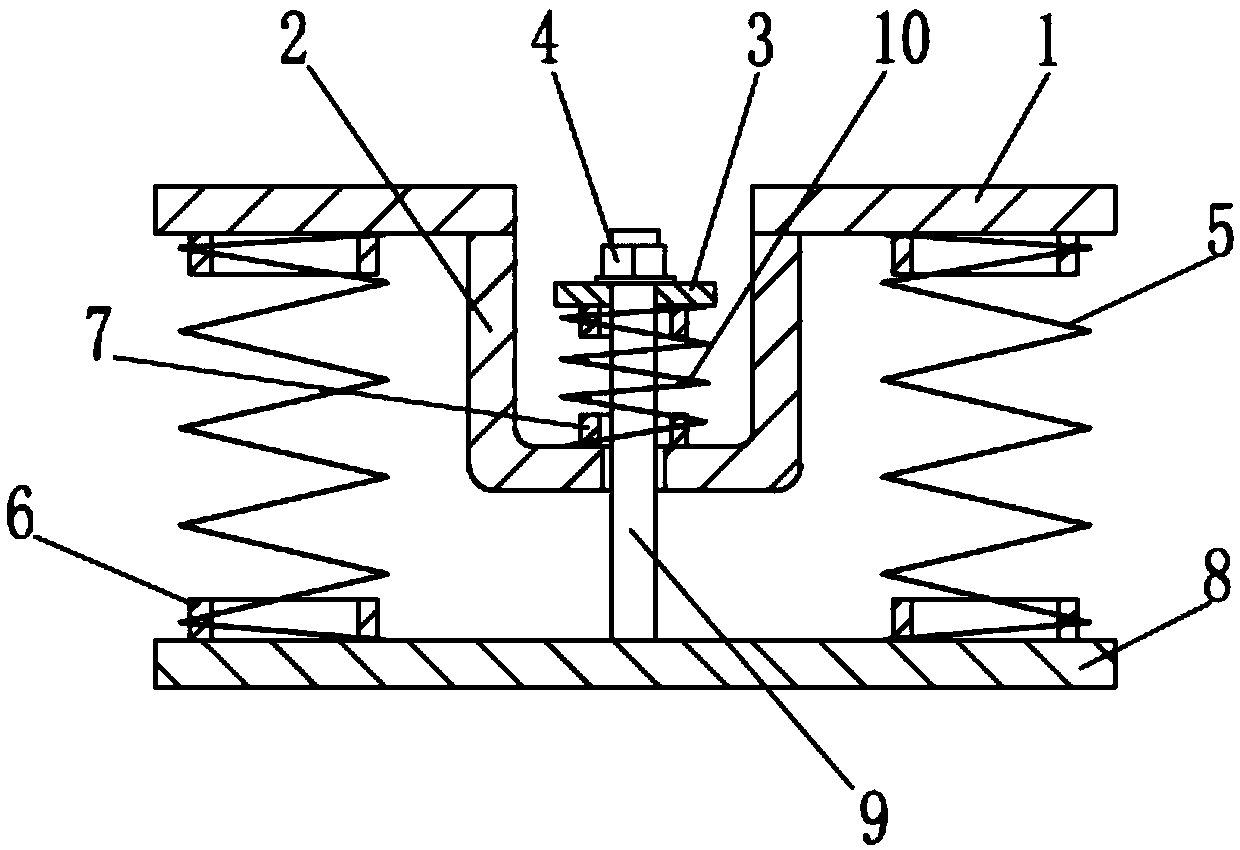
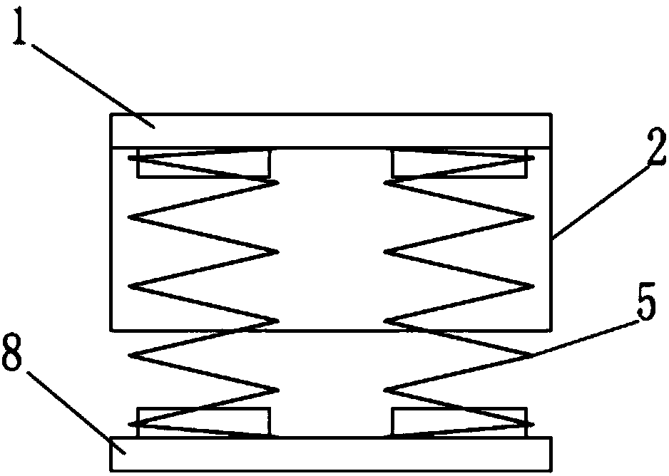
[0029] Such as figure 1 , figure 2 with image 3 The tensile elastic vibration isolator of the present invention shown includes a top plate 1, a base plate 8 and an elastic support element 5. The elastic support element 5 is specifically a metal compression spring composed of a helical steel spring. There are four helical steel springs in total. In addition, It also includes a back pressure elastic element 10, a back pressure plate 3 and a connecting rod 9. The back pressure elastic element 10 adopts a compression spring, specifically a helical steel spring. As for the limiting part of the pressure elastic element, the back pressure groove 2 is integrally provided on the top plate 1 , and the back pressure elastic element 10 is limited in the limiting groove 2 by the limiting part on the top of the connecting rod 9 . The limiter is a lock nut 4, and the corresponding connecting rod 9 top is provided with a threaded connection section, and the counter pressure plate 3 is arr...
Embodiment 2
[0034] Such as Figure 5 with Image 6 The difference between the tensile elastic vibration isolator of the present invention shown in Embodiment 1 is that the back pressure chamber 12 made by welding steel pipes and steel plates is integrally arranged on the top plate 1, and the back pressure plate 3 and the back pressure elastic element 10 are arranged on the back pressure chamber. In the pressure chamber 12, for the convenience of installation and maintenance, the top plate 1 is provided with installation through holes 13 correspondingly. In addition, a damping device 11 is provided between the back pressure chamber 12 and the base plate 8, and the damping device 11 is specifically two hydraulic damping devices.
[0035] Compared with the technical solution described in Embodiment 1, in the technical solution described in this example, since the damping device 11 is arranged between the back pressure chamber 12 and the base plate 8, the product structure is more compact, a...
Embodiment 3
[0037] Such as Figure 7 The difference between the tensile elastic vibration isolator of the present invention shown in Embodiment 2 is that the damping device is specifically a viscous damping device, and the viscous damping device includes a damping cylinder 14 fixedly arranged on the base plate 8, and the damping cylinder 14 is provided with a liquid damping material 15, the liquid damping material 15 is specifically a liquid viscous damping, the back pressure chamber 12 is partly placed in the damping cylinder and the lower part of the back pressure chamber 12 is immersed in the liquid damping material 15.
[0038] Compared with Embodiment 2, in the technical solution described in this example, the back pressure chamber 12 is used as the moving body of the viscous damping device. The back pressure chamber 12 reciprocates and shears the liquid damping material 15 in the damping cylinder 14, which can quickly realize energy consumption, which has the advantages of large dam...
PUM
 Abstract
Description
Claims
Application Information
 - R&D
- Intellectual Property
- Life Sciences
- Materials
- Tech Scout
- Unparalleled Data Quality
- Higher Quality Content
- 60% Fewer Hallucinations
Browse by: Latest US Patents, China's latest patents, Technical Efficacy Thesaurus, Application Domain, Technology Topic, Popular Technical Reports.
© 2025 PatSnap. All rights reserved.Legal|Privacy policy|Modern Slavery Act Transparency Statement|Sitemap|About US| Contact US: help@patsnap.com


