Drain Interceptor Cleaning Device

A technology for cleaning devices and canals, which is applied in artificial waterways, water conservancy projects, constructions, etc. It can solve problems such as high labor intensity for workers, collapse of fences and canals, and blockage of canals, so as to avoid overflowing water flow, good interception effect, and not easy to be blocked Effect

Active Publication Date: 2018-09-28
CHONGQING JIZHI CHUANGXIANG IND DESIGN CO LTD
View PDF5 Cites 0 Cited by
  • Summary
  • Abstract
  • Description
  • Claims
  • Application Information

AI Technical Summary

Problems solved by technology

[0002] Small and medium-sized pump stations and small hydropower stations are common water conservancy and hydropower facilities in rural areas. They are equipped with long canals. Because they are located in agricultural planting areas and open air, there are often many leaves, weeds, branches, and even It is domestic garbage scattered in the canal; and once there is heavy rain, water mixed with a lot of garbage will quickly flow into the canal. If the garbage cannot be cleaned, they will not only block the duct on the canal, but will continue to flow into the canal. Collected in front of the pumping station or in front of the water turbine, resulting in damage to the pump blades or water turbine blades, resulting in serious consequences
[0003] At present, manual work is mostly used to clean up garbage in the canal. By setting up fences in the canal at intervals, and then manually inspecting and salvaging garbage at the fence at regular intervals, this manual cleaning of garbage is not only labor-intensive for workers, but also A strong sense of responsibility is required, and there is also a certain risk of drowning
And if the salvage is not timely and the fence is blocked, the water level will rise and the water in the canal will overflow, and the fence and the canal will collapse if it is serious.

Method used


Image

  • Drain Interceptor Cleaning Device
  • Drain Interceptor Cleaning Device
  • Drain Interceptor Cleaning Device

Examples


Embodiment 1

[0020] Below in conjunction with accompanying drawing and specific embodiment the present invention will be described in further detail:

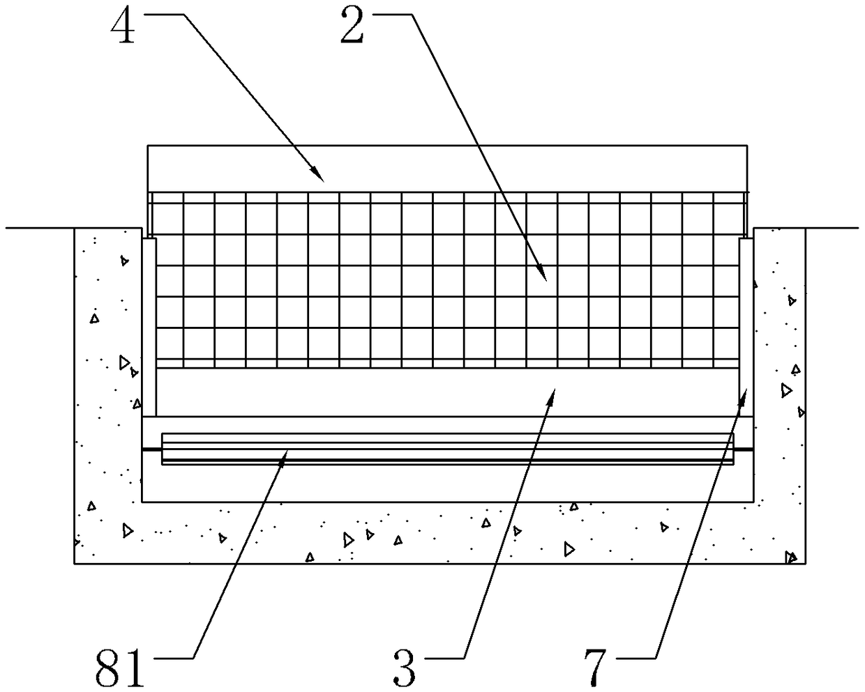
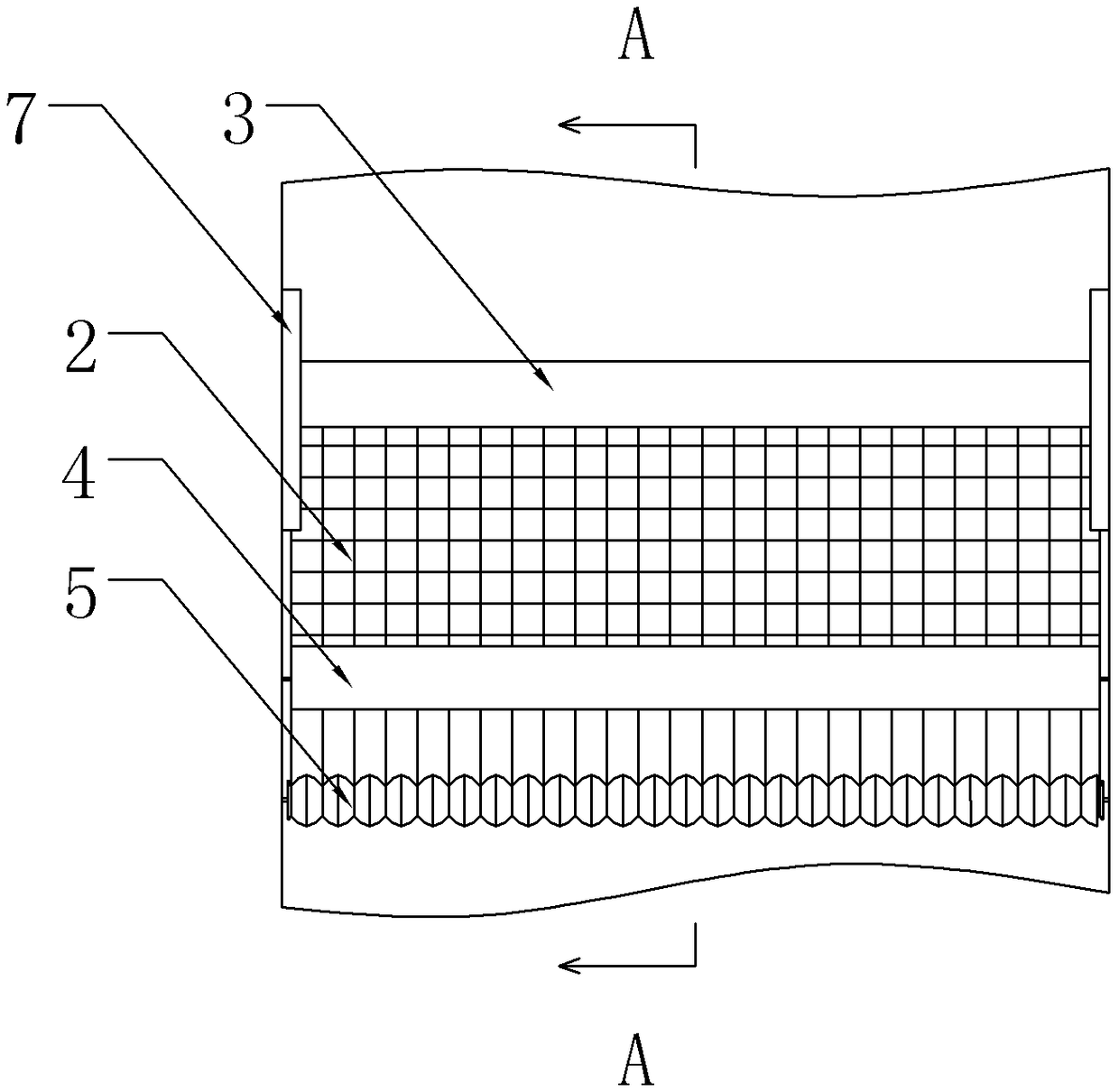
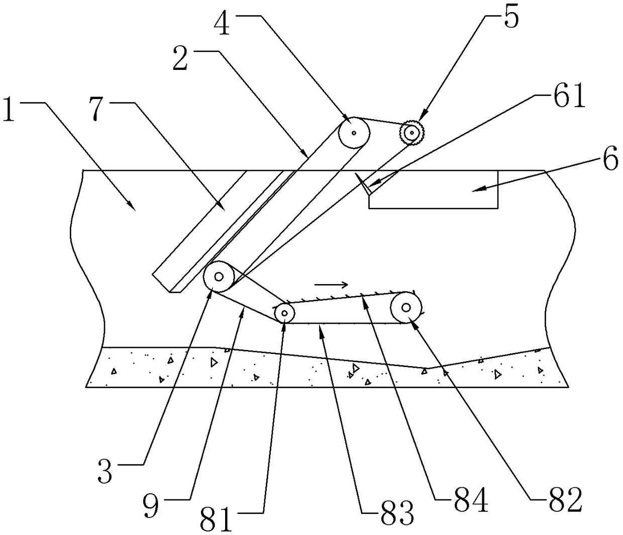
[0021] Such as figure 1 , figure 2 and image 3 Shown: the present invention provides a kind of water canal intercepting and cleaning device, comprises the intercepting net 2 that is arranged in the canal 1, and the intercepting net 2 is in the shape of a ring belt, and the intercepting net 2 is provided with the lower roller 3 of equal width sequentially from front to back, the front The upper roller 4 and the rear upper roller 5, the rotating shafts of the lower roller 3, the front upper roller 4 and the rear upper roller 5 are relatively fixed by a triangular bracket (not shown), and the bracket moves up and down along the chute of the side wall of the water channel 1. The upper drum 4 is located at the apex position, wherein the intercepting net 2 is composed of an inner weft net and an outer warp net. The length of the holes is sli...

Embodiment 2

[0024] The main structure of embodiment 2 is basically the same as that of embodiment 1, the main differences are:

[0025] The side edge of the sundries tank 6 is provided with comb teeth 61 inserted between the warp wire nets to clean up sundries carried between the warp wires.

Embodiment 3

[0027] The main structure of embodiment 3 is basically the same as that of embodiment 1, the main differences are:

[0028] The front power roller 81 and the rear power roller 82 are cylindrical roller cages. The inner wall of the annular belt 83 is provided with protrusions embedded in the gap between the roller cages. There is also a groove under the annular belt 83. The groove is V-shaped along the direction of water flow. .


PUM


Abstract

The invention relates to a water conservancy and hydropower facility, in particular to a water channel interception cleaning device. The device comprises an annular belt type interception net consisting of a weft net and a warp net; a lower roller, a front upper roller and a back upper roller are arranged in the interception net; the weft net is tensioned by the lower roller and the front upper roller; the warp net is tensioned by a triangle consisting of the lower roller, the front upper roller and the back upper roller; an impurity tank is formed below the front upper roller and the back upper roller; the lower roller is a closed hollow stainless steel barrel, and is provided with a capped water inlet in the end part; an interception plate is arranged between the lower roller and the side wall of a water channel; a front power roller and a back power roller are arranged behind the lower roller; an annular belt is arranged between the front power roller and the back power roller, and is hinged with a baffle plate; the baffle plate is inclined to one side opposite to the rotating direction of the annular belt; and the front power roller and the lower roller are connected through a conveying belt. The water channel interception cleaning device is excellent in interception effect, can automatically clean, and meanwhile, can reduce manual intervention.

Description

technical field [0001] The invention relates to a water conservancy and hydropower facility, in particular to a water channel interception and cleaning device. Background technique [0002] Small and medium-sized pump stations and small hydropower stations are common water conservancy and hydropower facilities in rural areas. They are equipped with long canals. Because they are located in agricultural planting areas and open air, there are often many leaves, weeds, branches, and even It is domestic garbage scattered in the canal; and once there is heavy rain, water mixed with a lot of garbage will quickly flow into the canal. If the garbage cannot be cleaned, they will not only block the duct on the canal, but will continue to flow into the canal. Collected in front of the pumping station or in front of the water turbine unit, resulting in damage to the water pump blades or water turbine blades, resulting in serious consequences. [0003] At present, manual work is mostly u...

Claims


Application Information

Patent Timeline
Patent Type & Authority Patents(China)
IPC IPC(8): E02B5/08
CPCE02B5/085
Inventor 吴睿段江舟
Owner CHONGQING JIZHI CHUANGXIANG IND DESIGN CO LTD
Why Eureka
Try Eureka