
A lake ice breaker

A technology of ice breaker and bottom surface, which is applied in the field of machinery, can solve problems such as damage to the ice surface, and achieve the effect of improving service life and preventing jamming

Active Publication Date: 2018-11-20
周旻洋
View PDF6 Cites 0 Cited by
  • Summary
  • Abstract
  • Description
  • Claims
  • Application Information

AI Technical Summary

Problems solved by technology

[0003] Obviously, the reason why the personnel use the ice breaker is because the ice surface is very thick, and the above-mentioned device destroys the ice surface through bricks. Extensive surface damage, leading to accidents

Method used


Image

  • A lake ice breaker
  • A lake ice breaker
  • A lake ice breaker

Examples


Embodiment Construction

[0021] The following will clearly and completely describe the technical solutions in the embodiments of the present invention with reference to the accompanying drawings in the embodiments of the present invention. Obviously, the described embodiments are only some, not all, embodiments of the present invention. Based on the embodiments of the present invention, all other embodiments obtained by persons of ordinary skill in the art without making creative efforts belong to the protection scope of the present invention.

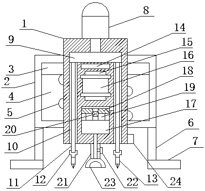
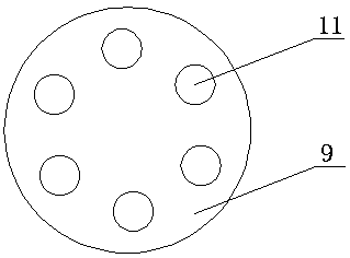
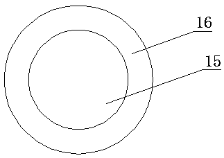
[0022] see figure 1 , figure 2 and image 3 , an embodiment provided by the present invention: an ice breaker for a lake surface, comprising a cylindrical shell 1 and a supporting shell 2, a set of limit rings 3 are fixed on the side of the cylindrical shell 1, and the support shell 2 A hollow structure 4 is provided inside, and the cylindrical housing 1 is placed inside the hollow structure 4 at the position of the limiting ring 3 , and the cylindrical hou...


PUM


Abstract

The invention discloses a lake surface ice breaker. The lake surface ice breaker comprises a cylindrical shell and a supporting shell, a limiting ring is fixed to the side face of the cylindrical shell, a hollow structure is formed in the supporting shell, the portion, located on the limiting ring, of the cylindrical shell is sleeved with the hollow structure, the portion, located in the hollow structure, of the cylindrical shell is sleeved with a spiral spring, the top of the spiral spring is fixed to the bottom face of the limiting ring, and multiple supporting legs are fixed to the bottom of the supporting shell. An ice layer is broken through cutting, as the contact area between the cutting portion and the ice layer is small, large-area breakage of the ice surface is avoided, and accidents caused by ice surface breakage are reduced. In addition, the spiral spring serves as a buffering element during force application, the contact area between a cutting component and the ice surface can be controlled, it is avoided that the cutting component gets stuck and then is broken, and the service life of the component is prolonged.

Description

technical field [0001] The invention relates to the technical field of machinery, in particular to an ice breaker for lake surfaces. Background technique [0002] Chinese Patent No. CN201310669170.4 discloses an ice breaker, which includes a sleeve, a push rod set in the sleeve and a drill bit connected to the working end of the push rod, and a number of foldable brackets are fixedly connected to the lower end of the outer wall of the sleeve; The upper end of the ejector rod is connected with a motor. The design of the drill bit of this device greatly reduces the possibility of the ice layer jamming the drill bit. The bracket can fix the device on the ice layer, which is more convenient for users to use; this device does not need to remove ice from fish ponds in a large area Just drill a few more holes on the ice layer to feed the fish and increase the oxygen in the water. When in use, the sleeve is fixed vertically on the ice layer, shake the hand, the drill bit spirals dow...

Claims


Application Information

Patent Timeline
Patent Type & Authority Patents(China)
IPC IPC(8): E02B15/02
CPCE02B15/02
Inventor 周旻洋
Owner 周旻洋
Learn More