

Floating driving device
A technology of a piling device and a piling machine, which is applied to sheet pile wall, construction, infrastructure engineering and other directions, can solve the problems of low piling efficiency, cumbersome and time-consuming, and time-consuming, and achieve the effect of improving piling efficiency.
- Summary
- Abstract
- Description
- Claims
- Application Information
AI Technical Summary
Problems solved by technology
Method used
Image

Examples
Embodiment Construction
[0017] The present invention will be further described in detail below in conjunction with specific embodiments and accompanying drawings.
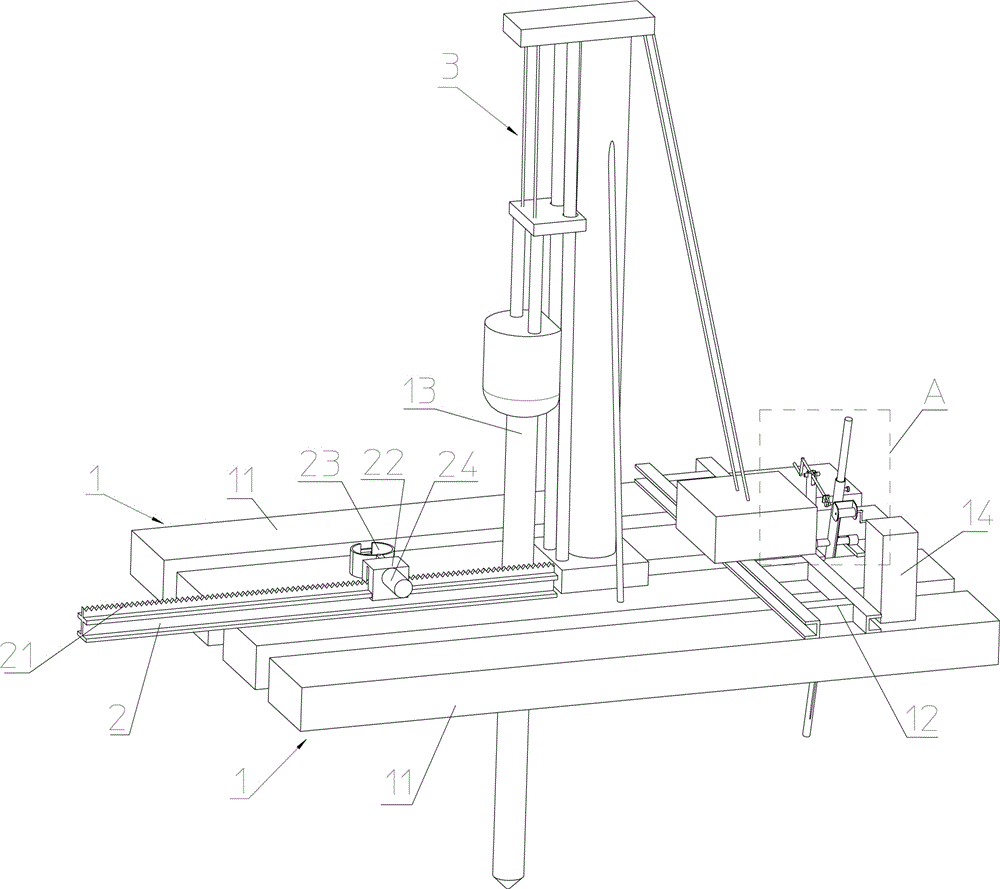
[0018] Such as figure 1 As shown, the piling device on water includes: two pontoon groups 1 placed side by side at intervals on the left and right, the two pontoon groups 1 are fixed into a whole by a crossbeam 12, and piling is arranged above the gap between the two pontoon groups 1 Machine 3, pile driver 3 can drive pile 13 into the underwater stratum through the gap between two pontoon groups 1, in the present embodiment, the tup of pile driver 3 is a diesel hammer, and the diesel hammer is a A hammer head commonly used in an existing pile driver, and a diesel hammer piling efficiency is higher; a guide rail 2 arranged along the front and rear direction of the gap between the two float tank groups 1 is arranged on the buoy box group 1 in front of the pile driver 3 , a rack 21 is arranged along the guide rail 2 on the guide rail 2, and...
PUM
 Abstract
Description
Claims
Application Information