
Excavator protecting method for mine cave

A technology for excavators and caverns, which is applied in the direction of mechanically driven excavators/dredgers, etc., can solve the problems of high rigidity of the backing plate, increase of backing plate thickness, and cracking of the surrounding welds, so as to reduce the amount of materials and reduce the distortion. Twisting deformation, avoiding the effect of tearing damage

Inactive Publication Date: 2017-05-31
重庆恒晟矿山设备制造厂
View PDF0 Cites 0 Cited by
  • Summary
  • Abstract
  • Description
  • Claims
  • Application Information

AI Technical Summary

Problems solved by technology

However, this structure has the following disadvantages, that is, when the arm body is under force, the arm body will bend and deform at the hinge point of the middle support, and the backing plate and anti-collision strip here will also bend and deform accordingly. Bending deformation must first overcome the rigid bending of the anti-collision strip, so when the rigidity of the anti-collision strip increases, the backing plate should also increase its rigidity accordingly; the increase in the rigidity of the backing plate will inevitably lead to an increase in the thickness of the backing plate, so that Prevents cracking of backing plates and their corresponding welds
Therefore, the disadvantages of this anti-collision device are: the rigidity of the backing plate is high, and the cost of the plate thickness is high; if the design value is improper, it will cause tearing of the backing plate and cracking of the surrounding welds

Method used


Image

  • Excavator protecting method for mine cave
  • Excavator protecting method for mine cave

Examples


Embodiment 1

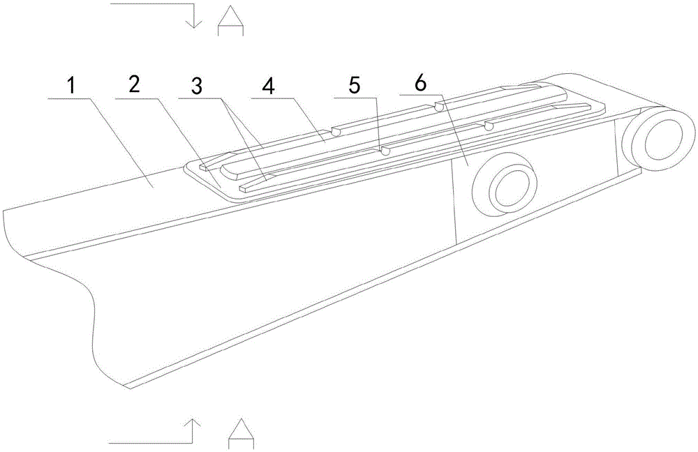
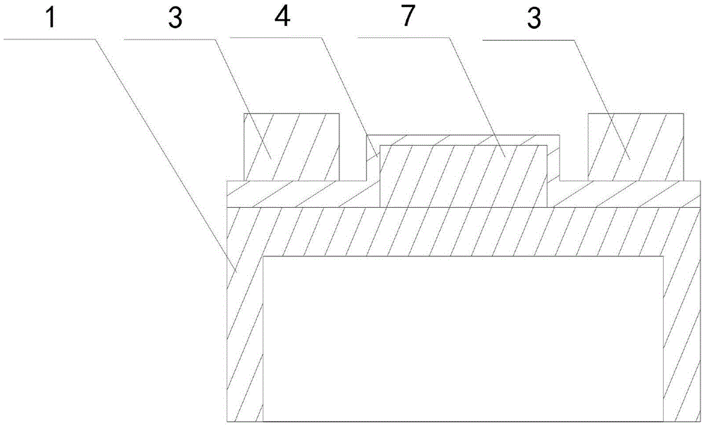
[0021] Such as figure 1 and figure 2 As shown, this embodiment includes a stick body 1 and a backing plate 2 welded on the inner wall of the stick body 1, and two strip-shaped strips are welded on the backing plate 2 along the axial direction of the backing plate 2. Reinforcing ribs 3, and stamping and forming a rectangular protrusion 4 parallel to the reinforcing ribs 3 in the middle of the backing plate 2 and along its bottom surface vertically pointing to the upper surface, the protrusion 4 is placed between the two reinforcing ribs 3 , and the horizontal height of the protrusion 4 on the upper surface of the backing plate 2 is less than the horizontal height of the reinforcing rib 3; a limit block 7 is also installed on the outer wall of the stick body 1, and the limit block 7 is connected to the The protrusion 4 fits inside.

[0022]When working, the stick body 1 bends, and the upper surface of the stick body 1 directly contacts or collides with the material to be exc...


PUM


Abstract

The invention discloses an excavator protecting method for a mine cave. The excavator protecting method for the mine cave comprises a bucket rod body and a cushion plate welded to the inner side wall of the bucket rod body; two strip-shaped reinforcing ribs are welded to the cushion plate in the axial direction of the cushion plate; a rectangular protrusion parallel with the reinforcing ribs is formed on the middle portion of the cushion plate in the direction where the cushion plate vertically points to the upper surface along the bottom face of the cushion plate in a punched manner; the protrusion is arranged between the two reinforcing ribs; and the horizontal height of the protrusion on the upper surface of the cushion plate is smaller than the horizontal height of the reinforcing ribs. The contact area between the protrusion on the middle portion of the cushion plate and soil is reduced, so that collision between materials and the protrusion is reduced; rigidity is improved when a bucket rod is bent, the outwards-protruding protrusion can effectively lower the rigidity of the cushion plate welded to the inner side wall of the bucket rod, the distortion deformation caused when the local stress of the cushion plate is not uniform is reduced, and therefore it is avoided that the cushion plate is torn and damaged in the using process.

Description

technical field [0001] The invention relates to an excavator, in particular to an excavator protection method used in a frame mountain cave. Background technique [0002] bulldozer It is an engineering vehicle with a large metal bulldozing knife installed in the front. When in use, put down the bulldozing knife to shovel forward and push mud, sand and stones, etc. The position and angle of the bulldozing knife can be adjusted. The bulldozer can complete excavation, soil transportation and unloading alone, and has the advantages of flexible operation, convenient rotation, and working surface Small, fast driving and other characteristics. It is mainly applicable from one to Three types of soil Shallow excavation and short transportation, such as site clearing or leveling, where the excavation depth is not large Foundation pit and backfill, build small height subgrade Wait. track The track-type tractor (also called crawler dozer) was successfully developed by Ameri...

Claims


Application Information

Patent Timeline
Patent Type & Authority Applications(China)
IPC IPC(8): E02F3/38
Inventor 王涛
Owner 重庆恒晟矿山设备制造厂
Learn More