
an electronic lock

An electronic lock and internal power supply technology, applied in the field of electronic locks, can solve problems such as electronic locks cannot be opened

Active Publication Date: 2019-08-20
上海图正信息科技股份有限公司
View PDF6 Cites 0 Cited by
  • Summary
  • Abstract
  • Description
  • Claims
  • Application Information

AI Technical Summary

Problems solved by technology

[0005] The embodiment of the present invention provides an electronic lock, which solves the problem that the electronic lock cannot be opened in a convenient manner

Method used


Image

  • an electronic lock
  • an electronic lock
  • an electronic lock

Examples


Embodiment 1

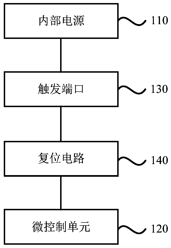
[0015] figure 1 A schematic structural diagram of an electronic lock provided in Embodiment 1 of the present invention, the electronic lock includes an internal power supply 110, a micro control unit 120, a trigger port 130 and a reset circuit 140;

[0016] Among them, the trigger port 130 is used for plugging in an external circuit;

[0017] The reset circuit 140 is connected with the trigger port 130 and the MCU 120 , and is used for generating a reset signal when the trigger port 130 is plugged into an external circuit, and transmitting it to the MCU 120 for reset.

[0018] Preferably, the external circuit is a battery or a conductor. A conductor can be any passive electronic component that conducts electricity, such as a wire or a metal conductor such as a coin.

[0019] Wherein, the internal power supply 110 is used to supply power to the electronic lock, and is located inside the electronic lock. Exemplarily, the trigger port 130 includes two pins, the first pin is co...

Embodiment 2

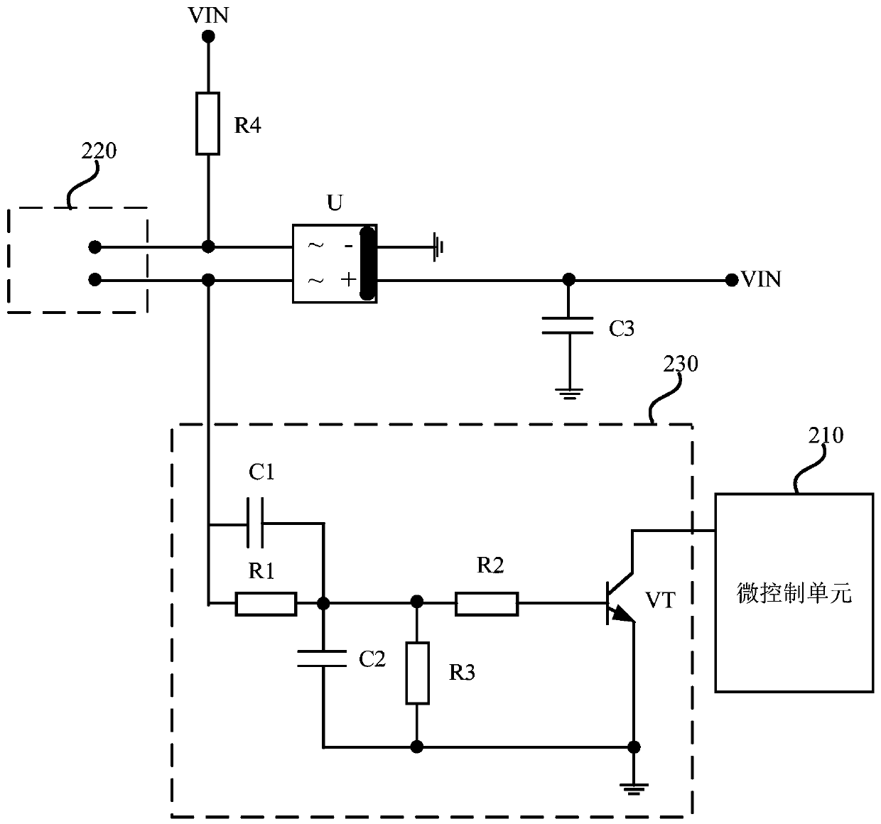
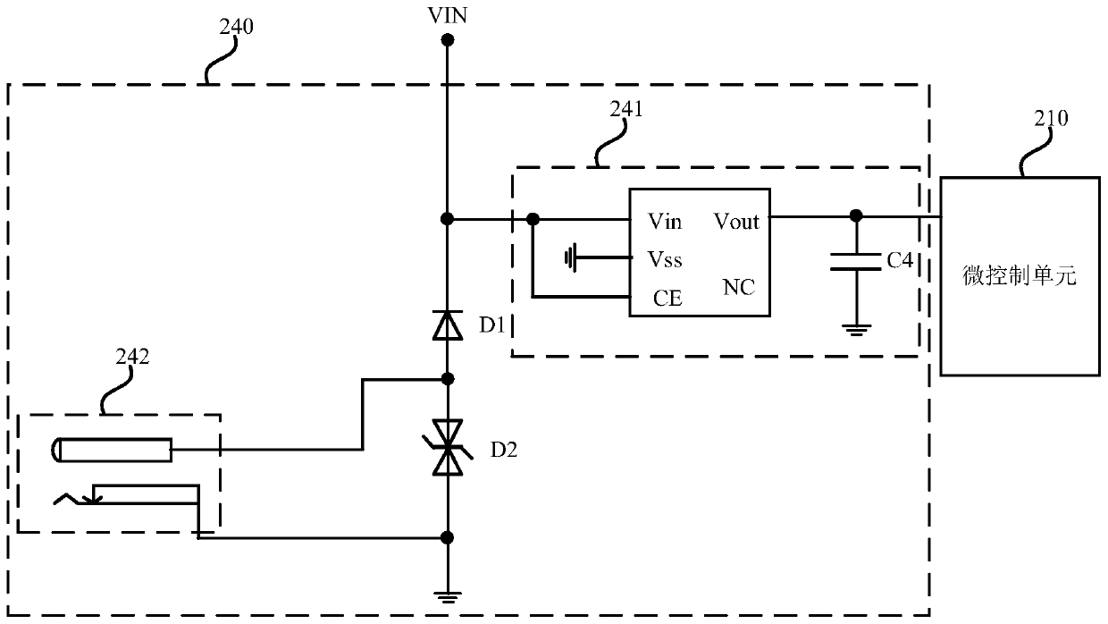
[0024] figure 2 It is a schematic structural diagram of an electronic lock provided by Embodiment 2 of the present invention. This embodiment is a further description of the above embodiments. see figure 2 , the electronic lock provided by this embodiment includes: an internal power supply, a micro-control unit 210, a trigger port 220, and a reset circuit 230, wherein the reset circuit 230 further includes a reset resistance-capacitance circuit and a switching transistor VT, wherein the reset resistance-capacitance circuit includes a parallel connection The reset resistor R1 and the reset capacitor C1 are connected between the trigger port 220 and the control terminal of the switch transistor VT, and are used to turn on the reset capacitor when the plugged external circuit generates a sudden voltage, and enable the control terminal to turn on the switch transistor VT ; When the switch transistor VT is turned on, a reset signal is generated and output to the micro control u...


PUM


Abstract

The invention discloses an electronic lock which comprises an internal power supply, a micro control unit, a triggering port and a reset circuit, wherein the triggering port is connected with an external circuit in an inserted manner; and the reset circuit is connected with the triggering port and the micro control unit, and used for generating and transmitting a reset signal to the micro control unit to perform resetting when the triggering port is connected with the external circuit in the inserted manner. The electronic lock can solve the problem that the electronic lock cannot be unlocked in a convenient and quick manner, so that user experience is improved.

Description

technical field [0001] The embodiment of the invention relates to circuit technology, in particular to an electronic lock. Background technique [0002] With the continuous development of science and technology, various electronic security devices and systems have been gradually integrated into people's lives, providing people with more sophisticated and perfect protection measures to ensure the safety of personal or family items and property. [0003] Among them, electronic locks replace traditional mechanical locks and are popularized in people's lives. Compared with traditional mechanical locks, electronic locks are more convenient to operate, and can provide people with more diverse security protection measures, making them safer. [0004] Usually, an electronic lock includes a battery, a microcontroller unit and other necessary peripheral circuits. Electronic locks may fail to open due to problems such as micro-control unit crashes or insufficient power supply voltage...

Claims


Application Information

Patent Timeline
Patent Type & Authority Patents(China)
IPC IPC(8): E05B47/00
Inventor 赵旭司永孝李龙
Owner 上海图正信息科技股份有限公司
Learn More