
Sliding door and window

A technology for sliding doors, windows and door leaves, applied in the field of doors and windows, can solve the problems of affecting the service life of door leaves, complicated installation of sliding doors and windows, uneven force on the upper slide rail, etc., so as to prolong the service life, realize the effect of heat insulation and low cost.

Inactive Publication Date: 2017-05-31
李东亮
View PDF6 Cites 2 Cited by
  • Summary
  • Abstract
  • Description
  • Claims
  • Application Information

AI Technical Summary

Problems solved by technology

[0003] The existing sliding doors and windows have certain disadvantages. First of all, the traditional sliding doors and windows mostly use "L"-shaped upper slide rails. When they are installed and used with the door leaves, on the one hand, the upper end of the upper slide rails is not uniformly stressed and unstable; on the other hand On the one hand, the friction between the upper slide rail and the door leaf is large, and long-term use will affect the service life of the door leaf; secondly, the glass door leaf of traditional sliding doors and windows uses an integrally formed reinforcement strip, which cannot be disassembled and does not have heat insulation at the same time. function; in addition, the structure, function and cost requirements of traditional sliding doors and windows are often not guaranteed at the same time, that is, sliding doors and windows with simple structure are easy to install and low in cost, but their firmness is not good; good but expensive

Method used


Image

  • Sliding door and window
  • Sliding door and window
  • Sliding door and window

Examples


Embodiment 1

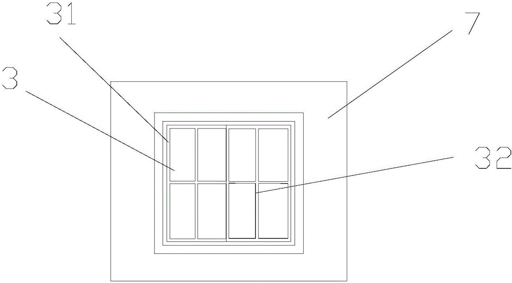
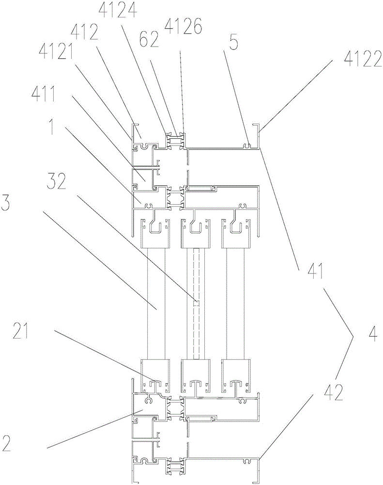
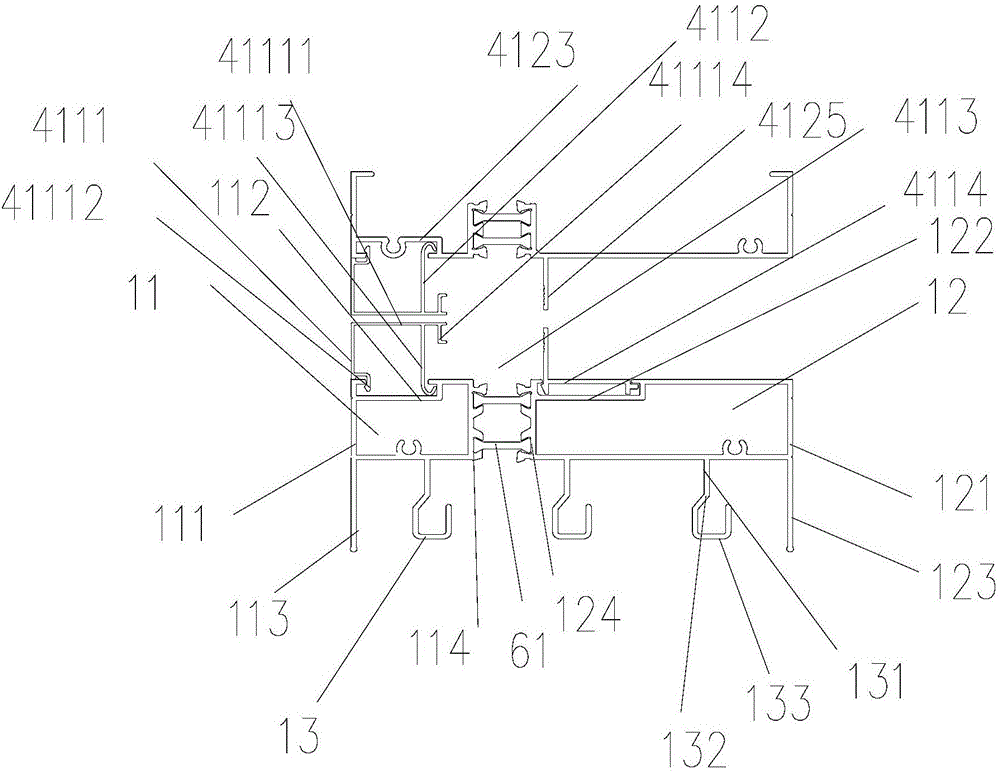
[0033] Such as Figure 1-5As shown, a sliding door and window of this embodiment has a simple structure and is easy to install, and includes an upper rail 1, a lower rail 2, and a glass door leaf 3; the upper rail 1 is located above the glass door leaf 3, and includes a left rail 11 and a right rail 12; The left rail 11 includes a first rectangular cavity 111 with a first groove 112 on the left side of the upper end. The left frame of the first rectangular cavity 111 extends downwards and is provided with a left support 113. The outside of the right frame of the left rail 11 has two second grooves. A heat insulating strip slot 114; the right rail 12 is arranged in parallel on the right side of the left rail 11, including a second rectangular cavity 121 with a second groove 122 at the upper end, and the right frame of the second rectangular cavity 121 extends downwards The right support 123 has two second heat insulation strip slots 124 on the outside of the left frame, and the...


PUM


Abstract

The invention discloses a sliding door and window which comprises an upper rail, a lower rail and a glass door leaf. The upper rail is located above the glass door leaf and comprises a left rail body and a right rail body. The left rail body comprises a first rectangular cavity provided with a first groove. A left frame of the first rectangular cavity is provided with a left support in a downward extending mode, and a first heat insulation strip slot is formed in the outer side of a right frame of the left rail body. The right rail body is parallelly arranged on the right of the left rail body and comprises a second rectangular cavity provided with a second groove. A right frame of the second rectangular cavity is provided with a right support in a downward extending mode, and a second heat insulation strip slot is formed in the outer side of the left frame. The lower rail and the upper rail are the same in structure. The lower end of the upper rail and the upper end of the lower rail are further separately provided with a fishhook-shaped upper slide rail and a T-shaped lower slide rail. The glass door leaf is located between the fishhook-shaped upper slide rail and the T-shaped lower slide rail and further provided with a detachable heat insulation reinforcing strip. The sliding door and window has the advantages that the sliding door and window is simple in structure, convenient to mount, good in firmness, low in cost and long in service life of the door leaf and is provided with the detachable heat insulation reinforcing strip.

Description

technical field [0001] The invention relates to the technical field of doors and windows, in particular to a sliding door and window. Background technique [0002] Sliding doors and windows have the advantage of not occupying indoor space, beautiful appearance and economical price. It adopts high-grade slide rails, which can be opened flexibly with a slight push; with large pieces of glass, it not only increases indoor lighting, but also improves the overall appearance of the building; the doors and windows are in a good stress state and are not easy to be damaged. [0003] The existing sliding doors and windows have certain disadvantages. First of all, the traditional sliding doors and windows mostly use "L"-shaped upper slide rails. When they are installed and used with the door leaves, on the one hand, the upper end of the upper slide rails is not uniformly stressed and unstable; on the other hand On the one hand, the friction between the upper slide rail and the door le...

Claims


Application Information

Patent Timeline
Patent Type & Authority Applications(China)
IPC IPC(8): E06B3/46E06B3/02E05D15/06E06B3/263E06B3/663E06B3/58
CPCE05D15/0621E06B3/025E06B3/263E06B3/4609E06B3/58E06B3/663
Inventor 李东亮
Owner 李东亮
Learn More