Drilling and completion fluid backflow tank with function of automatically crushing internal sedimentary rock debris

A technology for sedimentary rock and drilling and completion, which is applied in the field of drilling and completion fluid recirculation grooves, and can solve the problems of clogging and inconvenient cleaning and other problems

Inactive Publication Date: 2017-05-31
CHENGDU LAIBAO PETROLEUM EQUIP
View PDF6 Cites 7 Cited by
  • Summary
  • Abstract
  • Description
  • Claims
  • Application Information

AI Technical Summary

Problems solved by technology

[0003] The purpose of the present invention is to provide a drilling and completion fluid backflow tank that automatically breaks the internal deposited cuttings, so as to solve the problem of inconvenient cleaning due to the accumulation of cuttings in the backflow tank in the prior art, and to realize the convenient cleaning of accumulated debris in the backflow tank. purpose of cuttings

Method used


Image

  • Drilling and completion fluid backflow tank with function of automatically crushing internal sedimentary rock debris
  • Drilling and completion fluid backflow tank with function of automatically crushing internal sedimentary rock debris

Examples


Embodiment 1

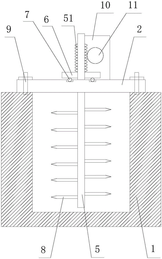
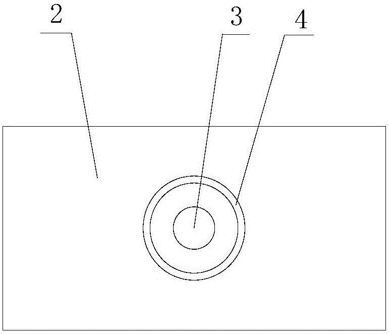
[0024] Such as figure 1 and figure 2The shown drilling and completion fluid backflow tank for automatically crushing internal deposits of debris includes a tank body 1, a plate 2 spanning the tank body 1 is erected at the upper end of the tank body 1, and a circular through hole 3 and a circular through hole 3 are opened in the center of the plate material 2. An annular groove 4, the groove 4 is concentric with the through hole 3, and the through hole 3 is located inside the ring of the groove 4; it also includes a stirring rod 5 passing through the through hole 3, the lower end of the stirring rod 5 The distance between the bottom of the tank body 1 is 5 to 10 cm; the stirring rod 5 is covered with a disc-shaped turntable 6, and the turntable 6 is fixedly connected to the stirring rod 5; the upper and lower surfaces of the turntable 6 are perpendicular to the stirring The axis of the stick 5, and the lower surface of the turntable 6 is provided with N rollers 7, and the N r...

Embodiment 2

[0026] Such as figure 1 and figure 2 The shown drilling and completion fluid return tank for automatically breaking the internal sedimentary debris, on the basis of Example 1, is aimed at the well wall with a diameter of 5 to 8 cm in the returned drilling fluid. Therefore, the lower end of the stirring rod 5 is set The distance from the bottom of the tank body 1 is 10 cm.


PUM


Abstract

The invention discloses a drilling and completion fluid backflow tank with a function of automatically crushing internal sedimentary rock debris. The drilling and completion fluid backflow tank comprises a tank and a stirring bar. A plate is erected at the upper end of the tank, a through hole and a groove are formed in the center of the plate and are concentric with each other, and the through hole is formed inside the groove; the stirring bar penetrates the through hole; a disc-shaped turntable sleeves the stirring bar and is fixedly connected with the stirring bar; the upper surface and the lower surface of the turntable are perpendicular to the axis of the stirring bar, rollers are arranged on the lower surface of the turntable, the turntable is positioned above the plate, and the rollers are positioned in the groove; a plurality of rod-shaped protrusions are further fixed to the surface of the stirring bar and are positioned below the plate; a worm is arranged on the portion, which is positioned above the plate, of the stirring bar; a motor is fixed to the upper surface of the plate, and a turbine is fixedly connected with a driving end of the motor, is matched with the worm and meshes with the worm. The drilling and completion fluid backflow tank has the advantages that the problems of accumulation and blockage of rock debris in existing backflow tanks in the prior art and inconvenience in cleaning the rock debris can be solved, and the purpose of conveniently cleaning the accumulated rock debris in the drilling and completion fluid backflow tank can be achieved.

Description

technical field [0001] The invention relates to the field of petroleum exploitation, in particular to a drilling and completion fluid backflow tank for automatically breaking internal deposited rock debris. Background technique [0002] Mud tank, also known as drilling fluid tank and backflow tank, is a tank that passes between the wellhead and the solid control equipment when the drilling fluid flows back from the wellhead to the sedimentation tank or mud tank during the drilling and completion of oil production. It is used to convey the mud with cuttings or formation sand returned from the well. The mud tank is the sampling place for drilling fluid logging, which is of great significance for mud logging. Liquid level sensors are installed in the mud tanks to monitor the amount of drilling fluid returned, so that it is convenient for engineers to judge whether there is overflow, lost circulation or kick, etc. at the first time. Therefore, the liquid level signal measured ...

Claims


Application Information

Patent Timeline
Patent Type & Authority Applications(China)
IPC IPC(8): E21B21/01B01F7/18B01F15/00
CPCE21B21/01B01F27/074B01F27/191B01F27/90B01F35/41B01F2101/49
Inventor 谭正怀
Owner CHENGDU LAIBAO PETROLEUM EQUIP
Why Eureka
Try Eureka